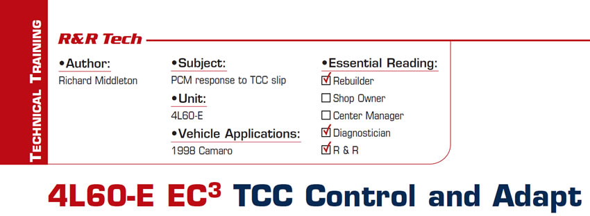
R&R Tech
- Subject: PCM response to TCC slip
- Unit: 4L60-E
- Vehicle Application: 1998 Camaro
- Essential Reading: Rebuilder, Diagnostician, R & R
- Author: Richard Middleton
While I was helping a co-worker repair a TCC slip, we analyzed some graphs and noticed some interesting info on how the PCM behaves and how it “sees” and adapts for a TCC slip.
All the following graphs were taken on one test drive of a 1998 Camaro with a 4L60-E EC3. The required fix was to overbore the TCC regulator valve and the AFL valve and replace them with oversize valves. They both showed significant wear using a wet-air-test technique. No other repairs were made and the transmission was not removed from the car. The fix isn’t the point of this article, though, because I’m sure most people reading this article are probably aware of valve-body wear issues that cause the TCC slip. The point is how advanced the computer strategy is and its ability to “see” and adapt to TCC slip.
These graphs were taken using a PC-based scan tool. I like to graph most vehicles in a similar manner as these graphs, with TCC slip and TCC percentage overlapped, VSS and TPS overlapped, and gear command showing so that you can see how the car is driven and what changes the computer makes based upon input from the driver.
Figure 1 is cold operation with no codes in the computer. This frame is normal. It shows accelerating from a stop, starting at frame #2500, and each gear change with TCC slip stair-stepping up as turbine speed changes with gear shifts. At frame 2620-2645 we let off the gas and coasted for a moment, and then we reaccelerated, allowing the TCC to apply. In frame 2660 and again at 2690 I step into the throttle more in an attempt to further load the TCC to make it slip. Notice that the TCC slip does go up corresponding to an increase in throttle just after frame 2690, but the computer raises TCC percentage slightly and slip is basically “under control” at 38 rpm by the end of the graph.
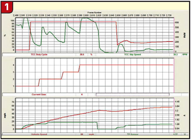
Figure 2 is shows a warm transmission cruising in 4th. In frame 3400 we raised throttle from 1.8 volts to about 2 volts, again loading the TCC. You will notice a slight TCC slip. After coasting through frames 3430-3490 we stepped into it again; the TCC percentage went up to 80% then gradually dropped to less than 50% in frames 3490 to 3520. This gradual-drop strategy is what I want to point out. It is interesting because I was increasing the throttle, giving more loads to the TCC, so you should expect that the computer would give more TCC percentage to hold on the clutch. But instead, the computer ramps the TCC duty cycle down until it creates a TCC slip. It is checking to see at what duty cycle the TCC will slip so it can command it just slightly above the minimum. This is a fuel-saving strategy to prolong the mechanical parts by running them at lower pressures. The computer demands as few amps through the solenoid as possible, thus applying minimal pressure to the TCC. This is an incredibly advanced strategy.
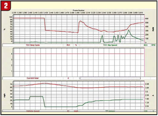
As our transmission continued to warm up, the problem started to show up again. In Figure 2, frames following 3530, the TCC slipped with a surge in and out as demonstrated by the spikes on the graph. We could feel the surging, and we could see it as a minor fluctuation on the tach. Notice that after the surging at frame 3585, the computer reacts with a sharp increase in TCC percentage despite no change in speed or throttle. This alone put the TCC back into control.
In Figure 3 the car is at normal temperature, and in frame 3025 we’re cruising along at about 1.8 volts on the TPS and the computer ramps up the TCC percentage from about 15% to about 55%.
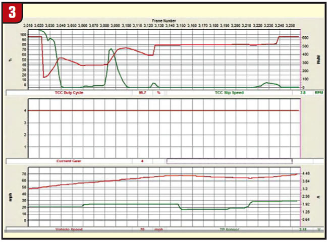
The TCC slip drops to zero. But, as soon as I load it up a little more, in frame 3060 the TCC slip goes up and in frame 3080 the TCC lets loose. The computer sees this and immediately reacts, raising the percentage from 40% to 75%, and the slip comes back into control and immediately in frame 3100 the computer starts ramping down the TCC again. This results in the slip in frames 3120-2130 and a corresponding command by the computer to increase the TCC duty-cycle percentage. Just after frame 3210 I apply additional load and TCC slips, and again the computer compensates, dropping the slip to zero. Eventually, after the car was at normal temp, the slip became enough that the computer triggered a TCC code.
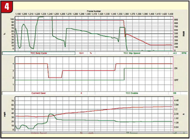
Figure 4 was taken on a hot test drive after we bored the AFL and TCC regulator and installed oversized valves. You can see at frame 1360-1430 that the computer ramps the duty cycle down to 25%. With the unworn circuits on the TCC regulator valve and AFL valve the computer is capable of keeping the slip in line with a 25% duty cycle. This gives lots of room for the computer to adapt and correct the slip.
The computer control strategy is extremely advanced on these transmissions, and learning about them is very interesting. Understanding how the computer behaves and how it adapts to problems is critical in understanding, diagnosing and repairing them.

Richard Middleton, the diagnostician at Certified Transmission’s location in Grandview, Mo., has been with the company for almost 20 years and is an ASE Master certified technician with L1. He is a previous recipient of the ASA Greater Kansas City Area Employee of the Year award.