Shift Pointers
- Author: Jesse Zacarias
- Subject Matter: Diagnosis
- Unit: FNR5
- Vehicle Application: 2008 Ford Fusion
- Issue: TCC slip and/or code P0771
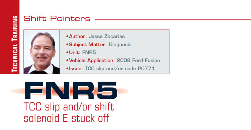
The FNR5 transmission can be found in most Ford and Mazda front-wheel-drive vehicles and has been with us for a while. One of the most-common calls we get on this transmission in the tech center at Valve Body Pro is for a code P0741 TCC slip and/or P0771 shift solenoid E stuck off. Recently we had a 2008 Ford Fusion with this problem. Figure 1 shows the SSA (SSPCA) increasing the modulation but no drop in rpm slip.
The shop had replaced the valve body twice, installed a new pump, bypassed the cooler and replaced the converter twice, but the problem persisted. Before we mention the fix, let’s see what is involved in applying the torque-converter clutch.
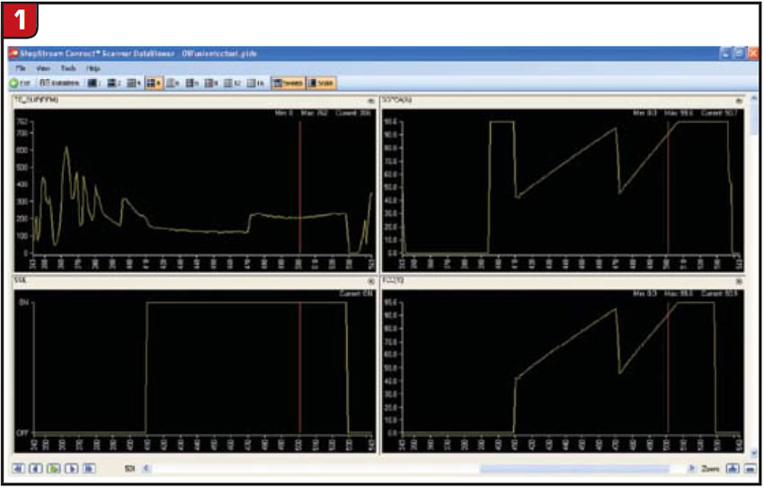
When the TCC is not engaged, fluid is present on both the front (TC/F) and rear (TC/R) of the torque-converter clutch, thus keeping the clutch from applying (Figure 2).
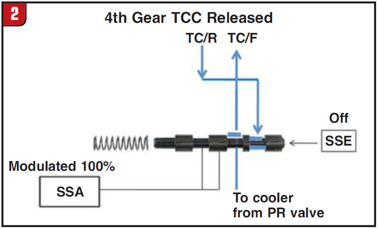
To apply the TCC in fourth gear, the SSE solenoid must be turned ON. The SSA solenoid, which is a PWM solenoid, is used to control the rate of apply. Since SSA is a normally open solenoid, when it is at 0% duty cycle it produces its maximum pressure, whereas at 100% duty cycle it produces 0 psi. If the TCC is to be applied directly without gradual application, the SSA will be ON 100% at the moment SSE is turned ON (Figure 3).
This ensures that no fluid will be present on the front side of the converter; that is, between the converter cover and the converter clutch.
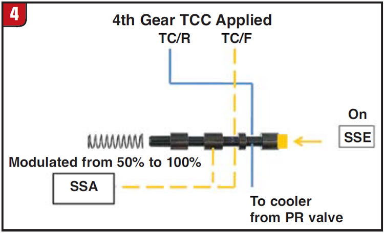
On the other hand, if the computer decides to apply the TCC gradually, SSA is modulated to about 50% when the SSE is turned ON. This allows the SSA solenoid fluid to be present between the converter cover and the torque-converter clutch, thus not allowing the clutch to engage. As the SSA is gradually modulated to 100%, the fluid present between the converter cover and the converter clutch is eliminated to fully engage the TCC (Figure 4).
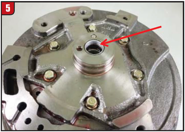
When rebuilding this unit you must look carefully for a worn-out valve-body bore at the TCC control valve and worn-out bushings at the pump stator on the location shown in Figure 5.
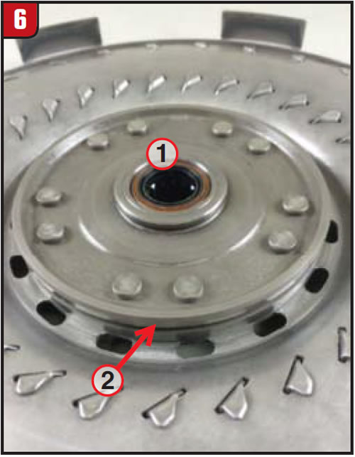
The other place that can cause the P0741 is inside the converter. Some of the most common, shown in Figure 6, are a damaged seal for the input shaft (1) and a worn or damaged sealing ring that seals the fluid between the turbine and the clutch and damper cover (2). A leak from these locations can allow fluid from the rear TCC to enter the front TCC and not allow the clutch to apply fully.
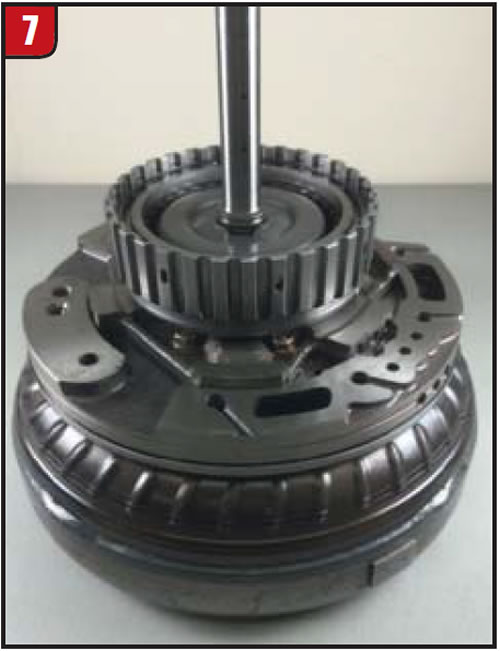
Unfortunately, we cannot see these seals, as they are inside the converter. Here is a test that you can do while building the transmission:
Place the complete pump assembly on the converter that you are going to use. Place the input-shaft/forward-drum assembly onto the pump (Figure 7).
Plug the cooler and torque-converter front feed (TC/F), marked by an X in Figure 8.
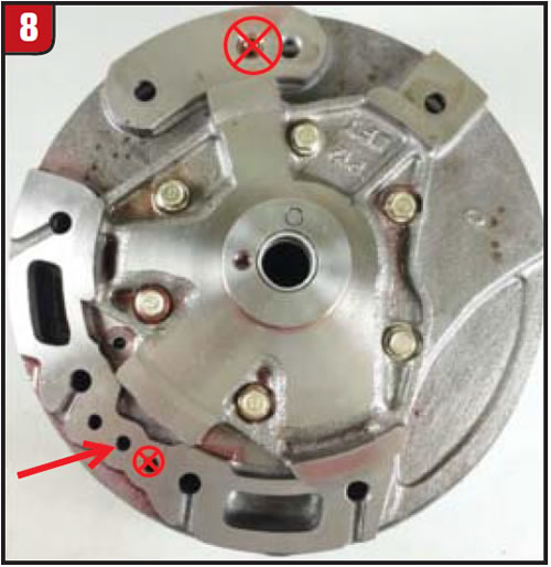
Gently blow regulated compressed air on the torque-converter rear feed (TC/R) while at the same time turning the forward drum/input shaft. If you are able to turn the drum with air applied, you have an internal leak that will cause a P0741.
On a properly working torque converter you should not be able to turn the shaft while applying about 10-18 psi of regulated compressed air. If you want to see a video of this go to Valvebodypros.com and under the Support tab click on Pro Tech Tips, then click on Video.
This was the problem with the 2008 Fusion mentioned at the beginning. Even with two different converters he had the same problem. With this test he was able to find a converter that held and the problem was solved.

Thanks to Aaron Hatfield from Bayview Transmission, Port Angeles, Wash., for his contributions to this article.
Jesse Zacarias is the owner of Elec-Tran Diagnostics (www.electrandiagnostics.com) in Gilroy, Calif., and part of the research-and-development department at Valve Body Pros.


