The Manifold Pipeway - Transmission Digest

The Manifold Pipeway

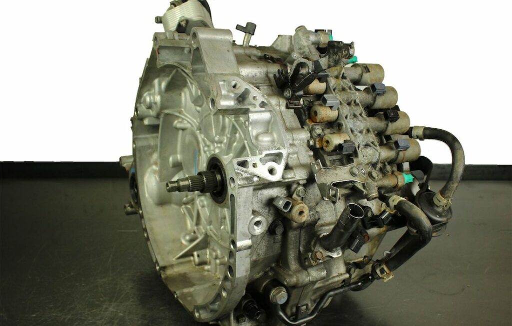
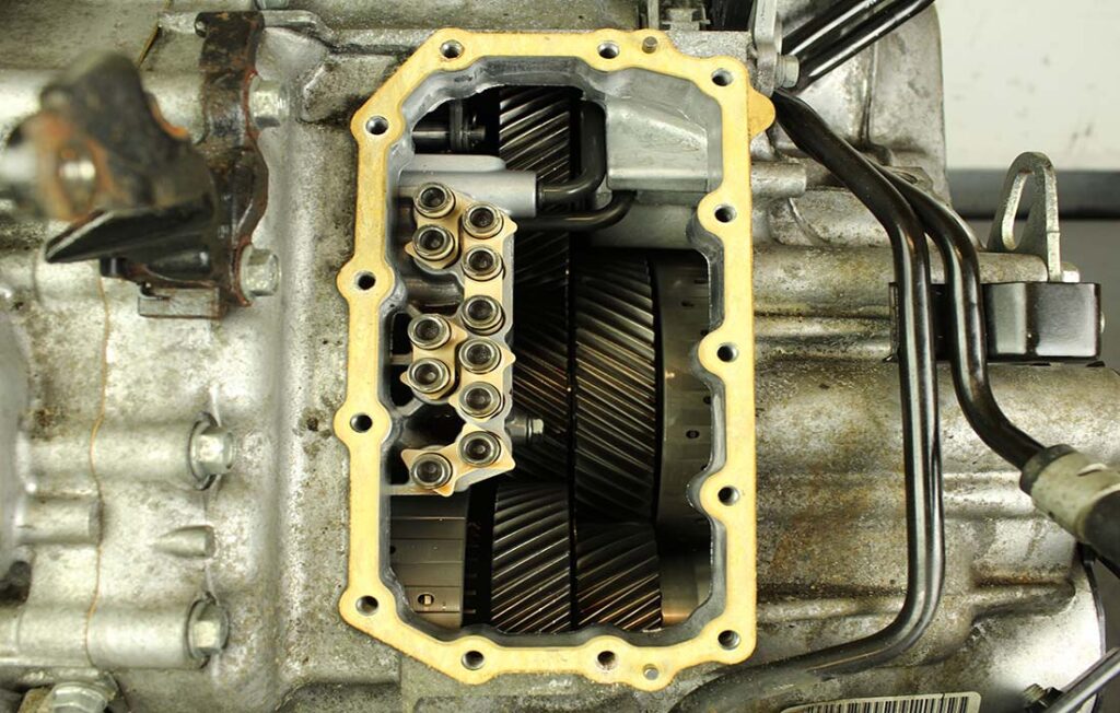
The Honda six-speed transmission has been on the bench of many specialty shops for one reason or another (figure 1). But, for those of you who have yet to lay your hands on one, mounted on the upper side of the unit is one of the largest, if not the largest solenoid and pressure switch assembly on a passenger car transmission you have ever seen (figure 2).

Figure 1
Figure 2

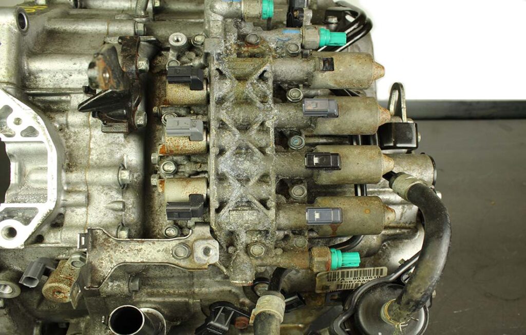
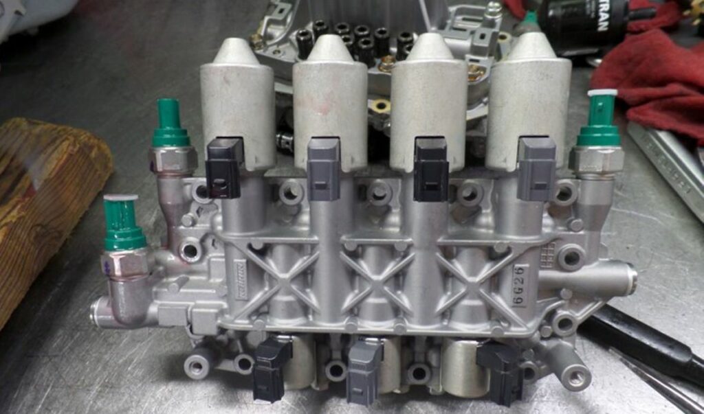
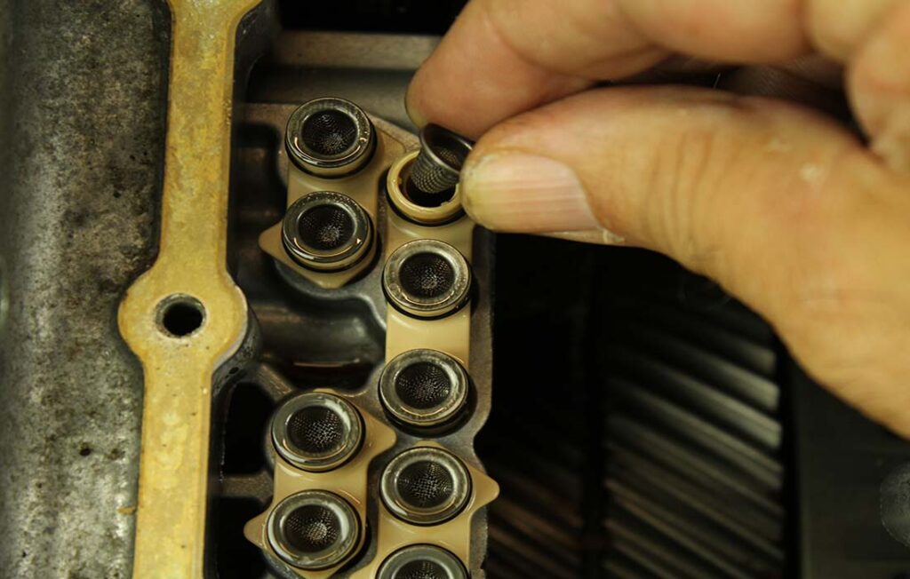
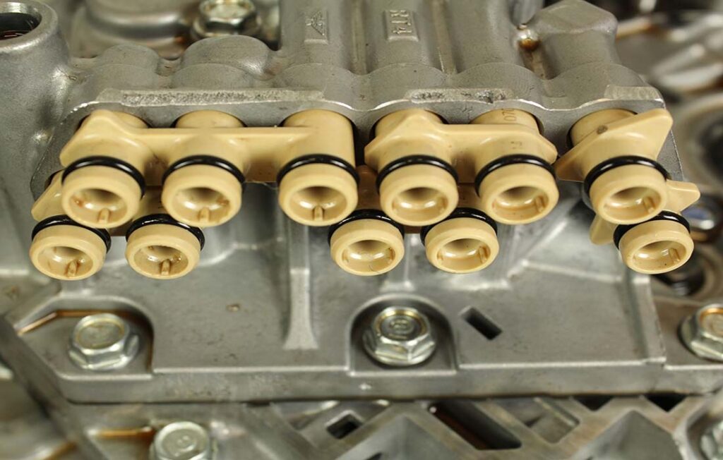
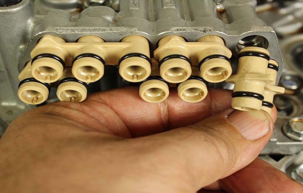
When this solenoid/pressure switch assembly is removed from the transmission (figure 3), you will see five plastic manifolds containing a total of eleven pass-through hydraulic circuit filter pipes. Each of these eleven pipes has its own filter screen cups in them (figure 4).  It is quite easy to lose a few of them as they are not integral to the pipe. However, they can be removed (figure 5). So, if you are not aware of this, they can fall out unnoticed and magically disappear.

Figure 3
Figure 4
Figure 5

These filter pipe manifolds are strategically keyway placed into an internally mounted adapter housing (figure 6). Honda calls this adapter housing “the manual valve body.”  The O-rings located closest to the end of these pipes is the side that presses into this manual valve body (figure 7).

Figure 6
Figure 7

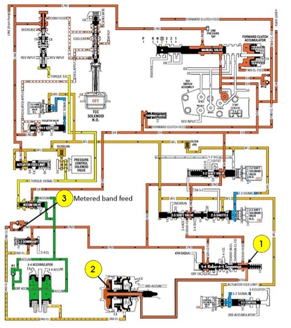
The question that comes up now and again from curious minds has been, “Are the functions of these filter pipes identified by Honda”? And the answer is both yes and no. “Yes,” in that they can be seen in hydraulic schematics showing their individual functions, but “No” in that they are not individually identified in their repair manual.   

In figure 8, each of these hydraulic filter pipes is numbered. These numbers are then placed next to their corresponding filter location in Honda’s hydraulic schematic seen in figure 9.

Figure 8
Figure 9

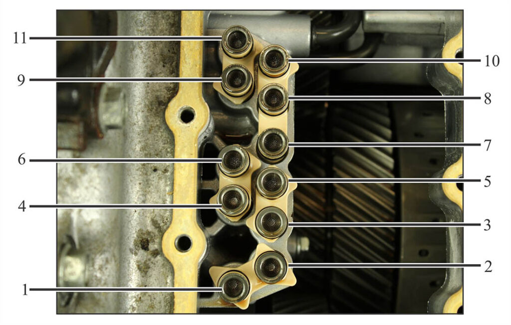
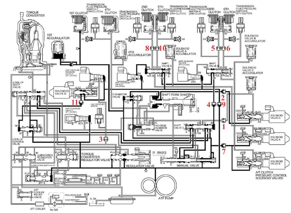
These are the hydraulic functions of each of these filter pipes in the manifold pipeway:

  • Filter # 1 filters the circuit between AT Clutch Pressure Control Solenoid Valve C, Solenoid Valve C Accumulator and Shift Valve C;
  • Filter # 2 filters the circuit between AT Clutch Pressure Control Solenoid Valve C and the Shift Fork Shaft;
  • Filter # 3 filters the circuit between Line Pressure Solenoid Valve A, Line Pressure Switch, Regulator Valve and the Lock-Up Shift Valve;
  • Filter # 4 filters the circuit between Shift Valve B and Shift Valve C;
  • Filter # 5 filters the circuit between Shift Valve B, Transmission Fluid Pressure Switch B and the 3rd Clutch;
  • Filter # 6 filters the circuit between Shift Valve B, Transmission Fluid Pressure Switch E and the 6th Clutch;
  • Filter # 7 filters the circuit between AT Clutch Pressure Control Solenoid Valve A, AT Clutch Pressure Control Solenoid Valve B and the Manual Valve (Pressure Supply;)
  • Filter # 8 filters the circuit between Shift Valve A, Transmission Fluid Pressure Switch A and the 2nd Clutch;
  • Filter # 9 filters the circuit between AT Clutch Pressure Control Solenoid Valve D, Line Pressure Solenoid A, Shift Solenoid Valve A, Shift Solenoid Valve B and the Manual Valve (Pressure Supply);
  • Filter # 10 filters the circuit between Shift Valve A, Transmission Fluid Pressure Switch D and the 5th Clutch; and
  • Filter # 11 filters the circuit between AT Clutch Pressure Control Solenoid Valve D and the Lock-up Shift Valve.

You May Also Like

Sherlock Holmes Approach to an AB60 No-Move Situation

The effectiveness in diagnosing automatic transmission malfunctions is an art form. Although there are similarities among the wide varieties of transmissions on the road, each transmission has its own peculiarities. Aside from having mechanical, hydraulic, and electrical hardware systems to contend with, software/programming issues and various vehicle platforms make diagnostics much more difficult.  Using scopes provides

ab60

The effectiveness in diagnosing automatic transmission malfunctions is an art form. Although there are similarities among the wide varieties of transmissions on the road, each transmission has its own peculiarities. Aside from having mechanical, hydraulic, and electrical hardware systems to contend with, software/programming issues and various vehicle platforms make diagnostics much more difficult. 

GM 6T40 Pump Identification Guide

The 6T40 was introduced in 2008 for General Motors front-wheel-drive cars in the Chevrolet Malibu and has gone through several changes throughout its three generations, specifically in the pump area. The 6T40 is closely related to the more lightweight 6T30 and the heavier duty 6T45 and 6T50. Generation one started phasing out during the 2012

Seeing the Forest AND the Trees

They say that the proverbial phrase “I couldn’t see the forest for the trees” means that a person or organization cannot see the big picture because it focuses too much on the details. Related Articles – TASC Force Tips: Diagnosing 8L45 & 8L90 Shift Complaints – TASC Force Tips: Hydraulics Fundamentals: Check Valves – Shift

8L90 Vacuum Testing

Below are the diagrams for vacuum testing GM 8L90 transmissions. Note: OE valves are shown in rest position and should be tested in rest position unless otherwise indicated. Test locations are pointed to with an arrow. Springs are not shown for visual clarity. A low vacuum reading indicates wear. For specific vacuum test information, refer

4L60E Harsh 1-2 Shift

The 4L60E transmission platform has been in service from 1993-2015; that’s 22 years. It amazes me when a transmission that has been around for this long can throw a new twist on a common problem and blindside you. Let us have a look at the systems and potential problems in a 4L60E that can cause

Other Posts

Ford 8F35 maintenance tips: Planetary failure and no-pressure conditions

Our shop has had several vehicles come in with the Ford 8F35 transmission having planetary failure. Apparently, there was a run where the pinion needle bearings had a hardness problem (see Figure 1). Related Articles – Ford 8F24 mechanical diode failure – Back with force: ATSG is back in full swing to educate the transmission industry

Figure 12.
Shift Pointers: A Chrysler 300 no-shift complaint

The case study has to do with a 2009 Chrysler 300 C 5.7L Nag1 RWD with 71,923 miles on it (see Figure 1, above). Related Articles – 2024 State of the Powertrain Industry – Powertrain industry directory and buyer’s guide 2024 – A guide to common GM, Ford and Nissan programming issues It is based

Shift Pointers: What to do when the 62TE TRS tab breaks

How frustrating it is when on a hot summer day, as you go to open a nice cold can of your drink of choice, and the tab breaks off? You are outside, away from any tools to remedy the problem quickly. It now requires a MacGyver mentality looking around at the resources available to get

Going the extra mile: Proving your transmission repair suspicions

A 2003 Honda Pilot with a five-speed three-shaft transmission came into our shop with a customer concern that the vehicle had no power, and the “D” light was flashing. I first did a scan for codes to see what it came up with, and the scan tool returned four DTCs: P1298 (ELD voltage high), P0135 (H02S

RRfeature-1400