The 4L60E transmission platform has been in service from 1993-2015; that’s 22 years. It amazes me when a transmission that has been around for this long can throw a new twist on a common problem and blindside you. Let us have a look at the systems and potential problems in a 4L60E that can cause a harsh 1-2 shift.
1-2 Shift Control Functions:
- Failsafe operation
- Line pressure control problems
- Accumulator valve system
- Servo apply area
- 1-2 accumulator piston and spring
- #8 check ball, 2nd gear feed orifice
- Servo cushion spring
- 4-3 Sequence valve
- Line Pressure Problems
Line pressure boost control has been the Achilles heel of the 4L60E for a long time. Many of the harsh 1-2 problems are due to the TCC slippage complaints setting P1870-P0894 codes and putting the transmission into high line pressure mode. Once the TCC slippage problems have been addressed the other line pressure areas of concern are the ECM EPC solenoid driver failure, lean misfire conditions, MAF sensor problems and the EPC solenoid itself. Diagnosing line pressure problems on a 4L60E requires a pressure gauge and DVOM to measure the commanded EPC solenoid amperage. It is not advisable to rely on the EPC solenoid commanded amperage PID on the scan tool. Far too often the PID will display the proper commanded amperage when in fact it is wrong. This occurs when the ECM EPC solenoid driver has failed especially on the 1993-1997 models.
- Accumulator Valve System
The accumulator system is one of the systems used for controlling and influencing the 1-2 and 3-4 shift. The valve needs to be carefully inspected to make sure it is not sticking and that the spring is not cocked in the bore. See figure 1.
 |
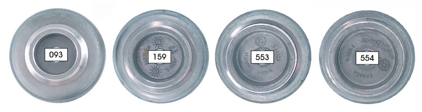
- Servo Area
There are four different OE servo sizes that are used with this transmission. Having the wrong apply area for the application can cause either a soft or slide bang 1-2 shift or a harsh 1-2 shift. With the exception of the 093 piston that is primarily used in Corvettes and HP Camaros most everything else that you are working on should have the 553 or 159 piston in it. See figure 2. NOTE: The 554 is intended for the 4 cylinder and the 2.8 V6 only.
 |
- 1-2 Accumulator Piston and Spring
The 1-2 Accumulator piston and spring came in many different configurations. In the early days, the piston was installed into the housing first with the spring on top. In the later years it was fitted with the springs in the housing first and the piston on top of the spring. When the Piston was installed into the housing first this setup created the band apply pressure against the spring tension, the heavier the spring tension the firmer the shift. With the springs in first (inverted) and the piston on top this created an opposite effect, more spring tension created a softer shift. The tension of the 1-2 accumulator piston springs and band apply orifice size are closely matched to the accumulator valve and spring in the valve body that we spoke of previously. Make sure the piston pin bore is not worn and there is no interference between the pin and piston. See figure 3.
 |
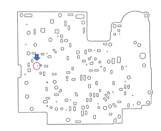 |
- The #8 Check Ball
The #8 check ball permits the band apply oil to flow through the .067”-.086” orifice in the separate plate during the 1-2 upshift. If the check ball is accidentally left out or misplaced the end result will be a harsh 1-2 shift. Inspect the separator plate feed orifice for proper sizing as many techs like to enlarge it. See figures 1 and 4.
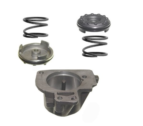
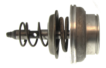
- Servo Cushion Spring
The servo has a heavy spring in between the piston and steel retainer plate. This cushion spring serves a vital role on the 1-2 shift accumulation, and it is an integral part of the 2nd to 3rd accumulator system. During repairs, it is advisable to remove the band pin from the servo to
verify that the band pin is not binding in the servo piston which would render the cushion spring inoperative. See figure 5.
 |
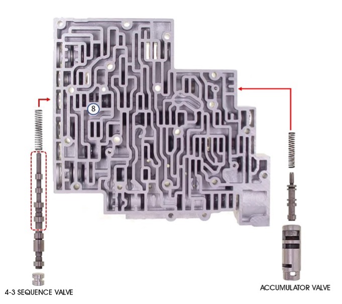
- 4-3 Sequence Valve
Once we have verified that the previously listed components 1-7 are in place and functioning correctly there is one last item that needs inspection. This item is the 4-3 sequence valve, see #1 in figure 6. The 4-3 sequence valve plays no role in controlling or regulating the 1-2 shift feel, however it can create a harsh 1-2 shift if the valve is stuck inboard. The harsh 1-2 occurs by allowing the 2-4 band apply oil pressure to be re-routed to the 4th gear servo apply piston, see fig #2 in figure 6. The apply area of the 4th gear servo piston is 6.108, this area is about .004% smaller than the Corvette servo piston apply area of 6.356.
The other contributing factors that come into play when the 4-3 sequence valve is stuck are:
1. The servo cushion spring is not utilized when the 4th piston applies the band as the 2nd servo does during a normal metered 1-2 shift.
2. The band apply oil to the 4th piston is full flow through the 4-3 sequence valve while the oil flow to the 2nd servo piston is metered through the .067-.086 orifice, see #3 in figure 6. The orifice it is not effective as the band is already applied ahead of the metered flow.
3. The same holds true for the 1-2 accumulator piston, it is working, it is just too late in relation to the band application due to the metering in the circuit.
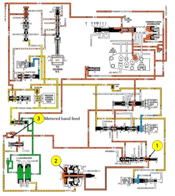
Figure 6
When the 4-3 sequence valve is stuck there will be 2-3 and 3-2 shift problems that will surface as well. In the big picture, the band is applied with a Corvette-style piston with no accumulation or no metering whatsoever, the shift is going to deliver a nasty 1-2 punch to say the least.


