TASC Force Tips
- Author: Gregg Nader
In past TASC Force™ Tech Tips, I have stressed the benefits of testing electrical circuits by measuring current draw. I have also commented that finding new information adds pieces to the puzzle and helps to bring the whole technical picture into better view. This month’s topic is an example of using current-draw testing to uncover an additional cause for 2-3 shift flare on 4L60-E transmissions.
In the past, hints and suggestions for causes of 4L60-E 2-3 flare have invariably been centered on problems inside the transmission. Some of the most-common causes are low line pressure and internal leaks of third-gear oil. More recently, information has come out about input housings with the 3/4-piston feed hole improperly machined in the lip-seal area. Another contender that now can be added to the list of possible causes for 2-3 shift flare on a 4L60-E is a bad computer.
This month’s problem vehicle is a 1998 GM truck with a flare on the 2-3 shift before and after overhaul, with no trouble codes. The shop installed a second valve body with all solenoids, but it didn’t help. Line pressure was normal in all ranges as well as when the flare occurred. When a new computer was tried, the problem went away. The puzzling thing was that line pressure was the same with both computers, so what was causing the flare? One clue was that the “B” solenoid data on the scanner sometimes would flash “short” when the problem occurred. This is when the ammeter came out to assist in diagnosis.
Most modern DVOMs give the option of checking current (amps). If you have never done current-draw testing, I encourage you to learn more by checking the manual for your DVOM, reading past Tech Tips (Transmission Digest, November 2002) or other recent tech articles about the newer mini clamp-on inductive amp probes. Checking amperage is neither complicated nor difficult and is often easier than resistance tests or other more-commonly performed circuit checks. Testing circuits while they are in operation is one of the most-effective ways of confirming a good circuit. Once you have become comfortable with the concept, it becomes a powerful diagnostic tool.
For this vehicle I tapped into the transmission +Positive power supply by replacing the ‘Trans’ fuse with the two leads of the DVOM. Now, all power for this circuit is flowing through the amp section of the DVOM and the circuit remains protected by the internal fuse in the meter. Figure 1 shows the setup using a conventional DVOM. With the key on and using a scan tool with bi-directional controls, the next step is to command third gear, which turns both “A” and “B” shift solenoids off on a 4L60-E. At this point, zero out the DVOM so the current draw from any other components sharing this circuit is canceled out and you are monitoring only current changes you command from this point on. Commanding fourth turns on only the “A” solenoid, while commanding second turns on only the “B” solenoid.
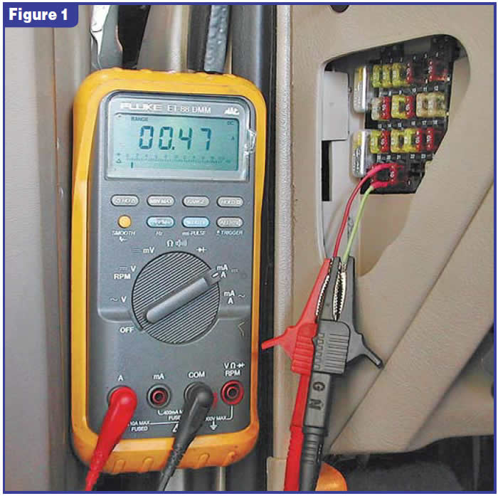
Using this simple DVOM setup, we watched the current draw change as each solenoid was turned on and off. Although the maximum current draw of the two circuits was almost identical, their behavior was not. When turned off, the “A” solenoid would drop to zero in a fraction of a second, whereas the “B” solenoid would take about two seconds to drop to zero. We recorded the behavior using the graphing capability of a Snap-on™ Vantage to get a closer look and to show you a picture of what we spotted on the DVOM. Figure 2 shows the difference when the “A” and “B” solenoids were compared. When the computer did not turn the “B” solenoid off cleanly, it would not exhaust its oil fast enough and the 2-3 shift valve would move gradually instead of moving crisply from one position to the other. This allowed the 2-4 band to come off momentarily before the 3-4 clutch applied, resulting in a 2-3 flare.
What causes this problem inside the computer? There are no physical contacts that open or close like in a relay. All the solenoid controls or output drivers are solid-state circuitry. It could be anything from a decaying capacitor to a silicon chip going bad because someone sneezed in the clean room when it was being made. I have seen two vehicles with this problem locally, so there is a good chance there are more bad computers out there. So, if you run across a 2-3 flare, keep in mind the computer as a possible cause.
Thanks to Jeff Davis at Rockenbach Chevrolet and Jon Glatstein of ATSG for their contributions to this article.

Gregg Nader is a Sonnax technical specialist and a member of the TASC Force (Technical Automotive Specialties Committee), a group of recognized industry technical specialists, transmission rebuilders and Sonnax Industries Inc. technicians. ©2006 Sonnax


