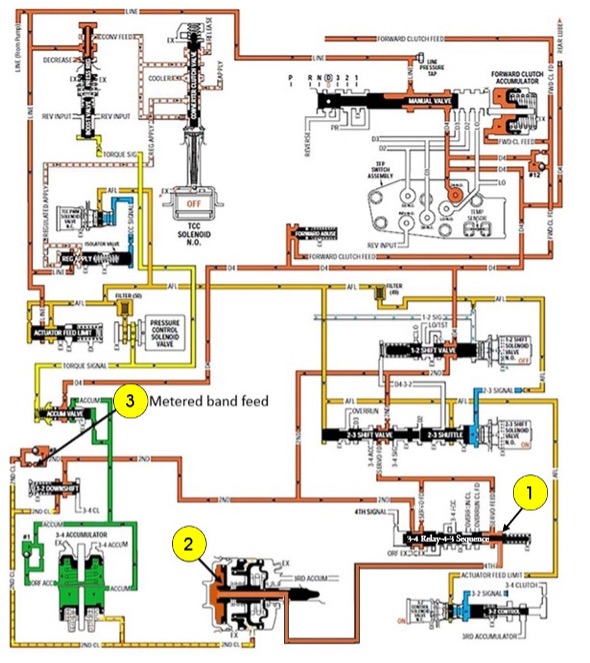
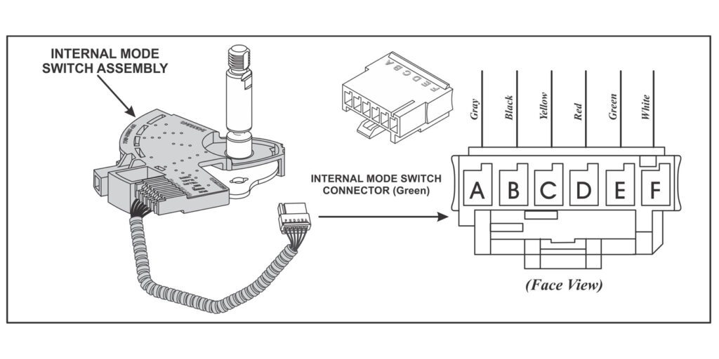
The 6T70’s “Internal Mode Switch” (IMS) is a sliding contact switch that connects to the manual valve, with an electrical connector that plugs into the control solenoid body and TCM assembly. There are four inputs to the TCM from the position switch assembly that indicates which transmission gear range has been selected. The state of each input can be displayed on a scan tool.
The four input parameters are Signal A, Signal B, Signal C, and Signal P (Parity). A fifth input signal “N” (P/N Start) does not input to the TCM but goes directly to the ECM to determine a Park/Neutral state and allow the engine to be started. Routing Signal N to the ECM will allow the engine to be started, even with a dead TCM.
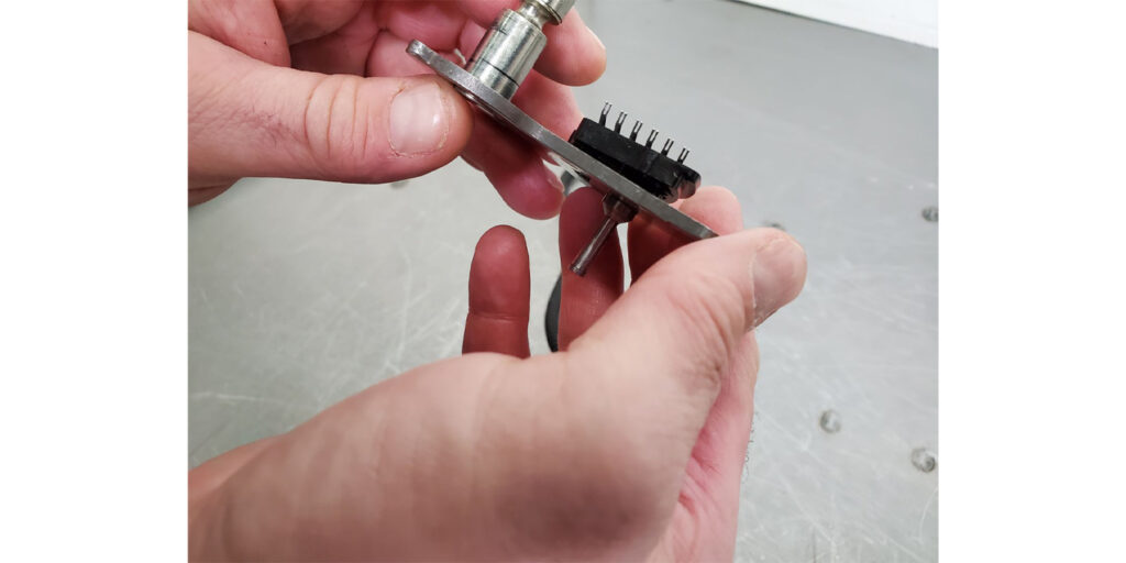
If the TCM detects an improper signal from the Internal Mode Switch (IMS) assembly, a DTC P1825 code for an invalid signal will be activated. After rebuilding the transmission, this invalid signal code may set immediately. What typically occurs that causes this malfunction is during disassembly of the switch, the retention tabs pop off (figure 1).
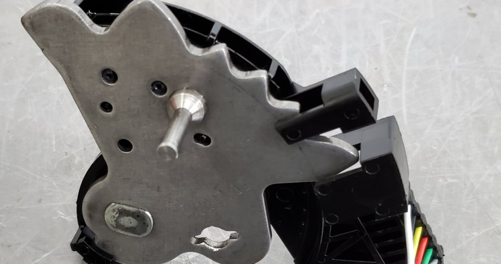
This allows the switch assembly to spread open during operation preventing the metal tension fingers from having proper pressure on the contacts inside the IMS. Aside from needing to remove the transmission from the vehicle, there is a simple fix for this problem with not having to purchase a new assembly.
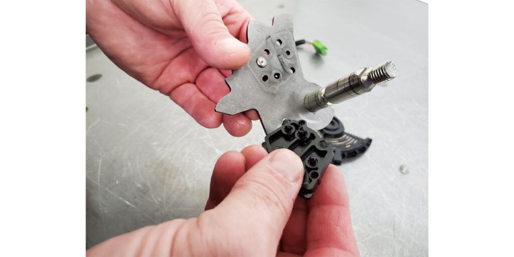
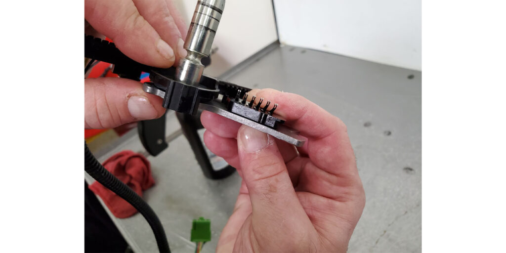
Step one is to disassemble the switch (figure 2). You will see how easy it is once you do it. Inspect all the parts and contacts to be certain no other problem is lurking within the switch aside from the popped tab tops.
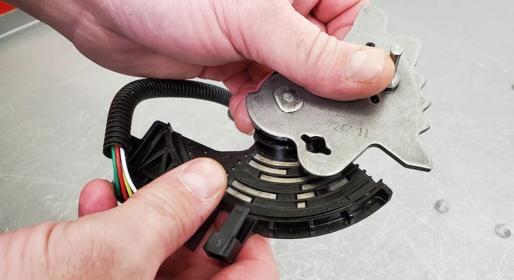
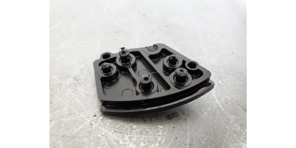
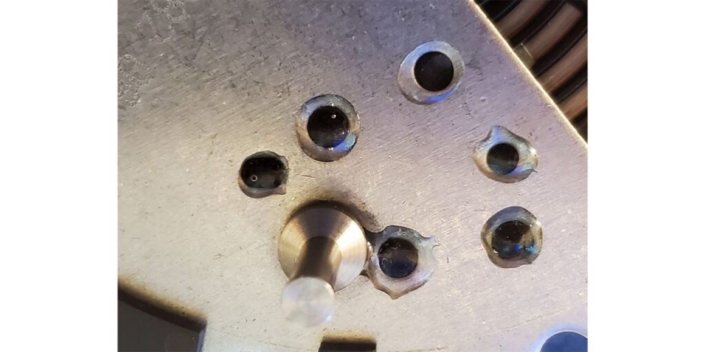
If all the tab tops are popped off, the tension plate will separate from the detent assembly (figures 3 and 4). Figure 5 shows that one tab is completely missing while three tabs have their tops popped off. There are also two alignment pins as part of this tension plate.
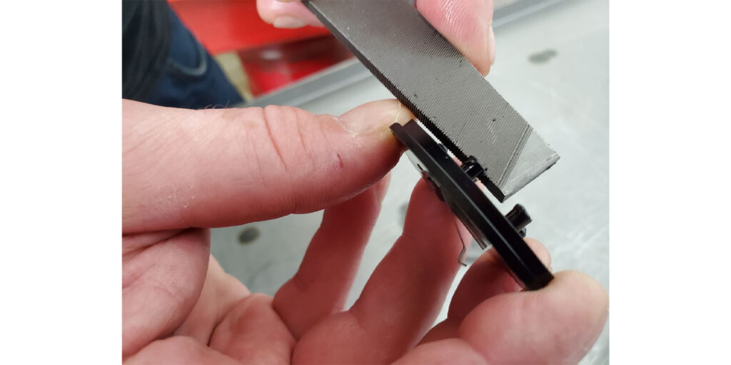
Using a file or equivalent tool, dress up the tops of the tabs as seen in figure 6. Clean all the parts ensuring that they are oil-free (figure 7) and reassemble the switch (figure 8). During the reassembly process, make certain the tension plate remains flat on the detent assembly and the metal tension fingers do not get bent out of position.
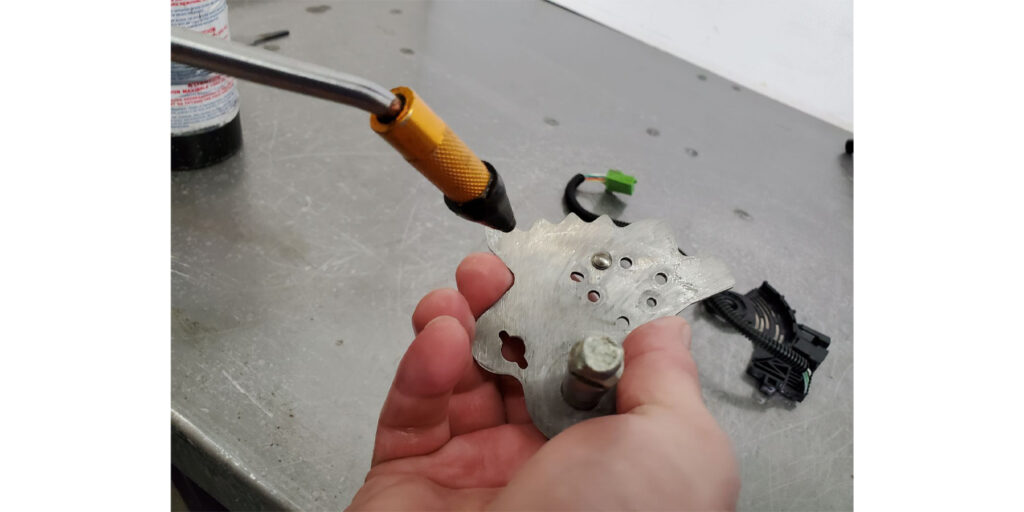
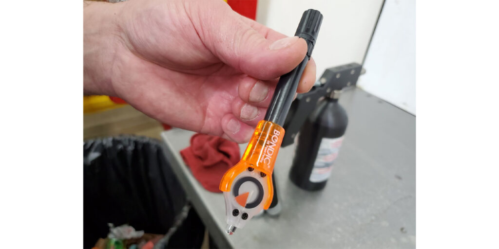
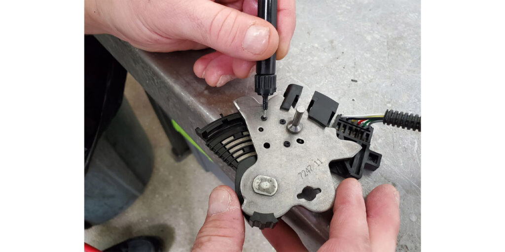
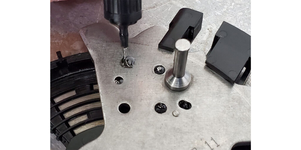
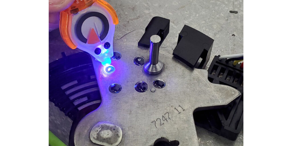
Once the switch is assembled, use UV liquid plastic welding to secure the tension plate to the detent assembly such as one from Bondic as seen in figure 9. Carefully drop the glue that comes with the kit onto each of the tabs including the tops of the alignment pins as seen in figures 10 and 11. Then cure using the UV light as seen in figures 12 and 13.
To double-check your work to verify the integrity of the switch’s signals, continuity checks can be easily made using an ohmmeter with figures 14 and 15 as your guide. Terminal A is the ground path where the negative lead can be placed.
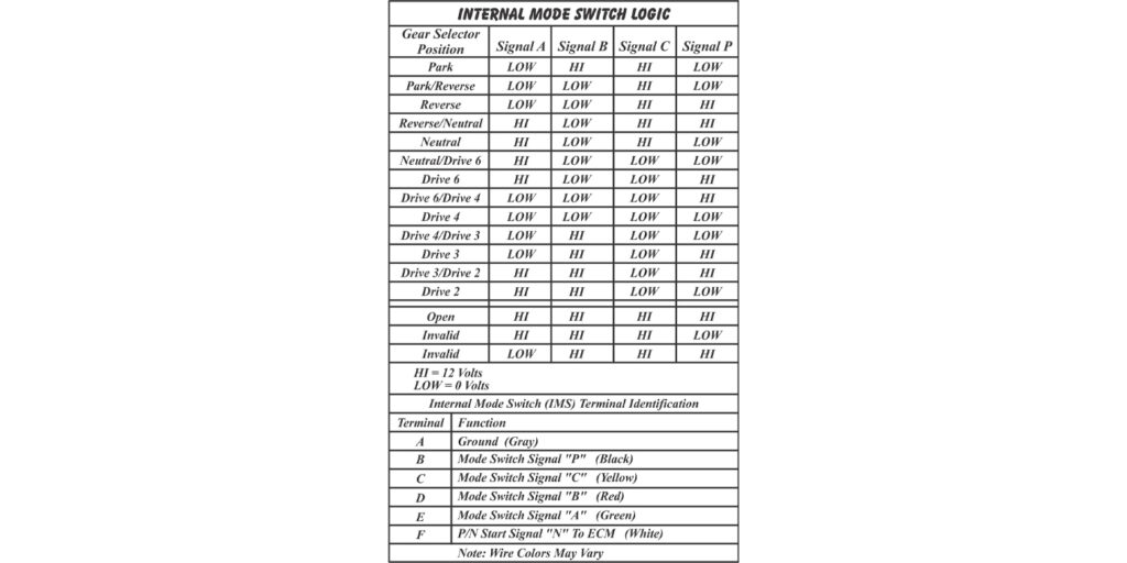
To check Signal A for example, place the positive lead on terminal E. Using the chart in figure 15, there should be continuity in each of the gear ranges marked LOW. For all the HI’s it should read open circuit. Once all circuits have been verified as good, the switch is ready to be installed into the transmission.