Body of Evidence
- Subject: No reverse
- Unit: FNR5
- Vehicle Application: Ford Fusion
- Essential Reading: Rebuilder, Diagnostician
- Author: Joe Cangelosi
It is not too often that you see a no-reverse concern caused by a bad solenoid or by a valve-body problem that does not affect any forward upshifts. Generally you’ll see this only on valve bodies that have a reverse-inhibit function, such as the 5L40 or JF506. There are always exceptions, though. We recently had an FNR5 do exactly that. In this instance it was a bad shift solenoid, but not one obviously connected to reverse.
The FNR5 uses six shift solenoids to control upshifts and downshifts and TCC apply. Shift solenoids A, B and C are normally open (pressure flows through when they’re de-energized) duty-cycle-type solenoids. Shift solenoids D, E and F are normally closed (do not allow pressure to flow when de-energized) on/off-type solenoids.
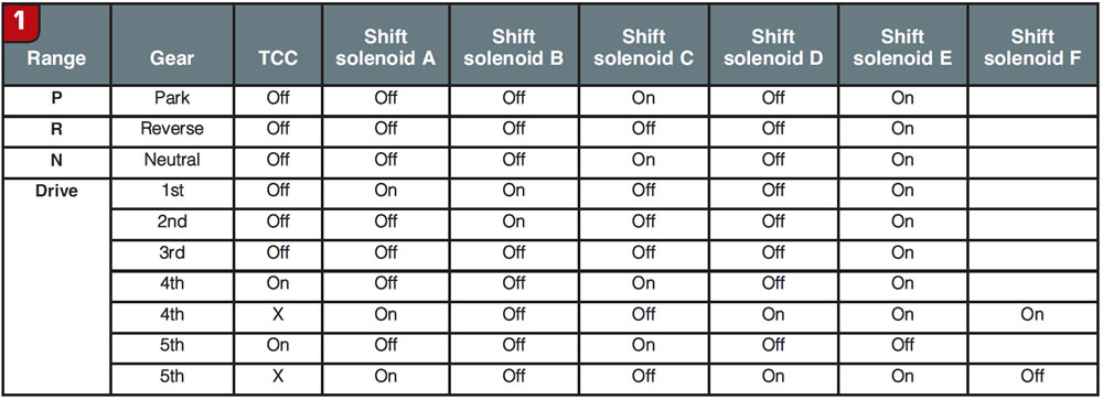
If you look at the solenoid application chart in Figure 1, you’ll find that only shift solenoid F (SSF) is on in the reverse position. SSF is on the secondary valve body and controls the position of the 4-5 shift valve. The 4-5 shift valve in turn routes line pressure to either the reduction brake in reverse and 1st through 4th gears or the direct clutch in 5th. At first glance it seems like a no-brainer. If SSF is stuck closed the 4-5 shift valve would not move, the reduction brake would not come on and there would be no reverse. First through 4th gears would work fine because the No. 2 one-way clutch would hold the secondary sun gear instead of the reduction brake. In the forward ranges, the reduction brake is what gives you engine braking. There is one problem with this theory, though. There is a case passage that feeds reverse-clutch pressure to the secondary valve body to move the 4-5 shift valve. This allows the reduction brake to apply even if SSF is not working.
Next, if we look at an oil-circuit diagram for reverse (Figure 2), we see that shift solenoid B (SSB) is sending solenoid pressure to the low/reverse clutch. So let’s take a look at what happens if SSB is stuck closed. Obviously, the low/reverse clutch would not apply and we would have no reverse. One problem with this is that in the forward ranges SSB applies the 2-4 servo. The low/reverse shift valve is what allows the solenoid to perform double duty. If the solenoid is stuck closed then the unit would not have 2nd and 4th gears. Remember, we said earlier that the problem did not affect any of the forward upshifts.
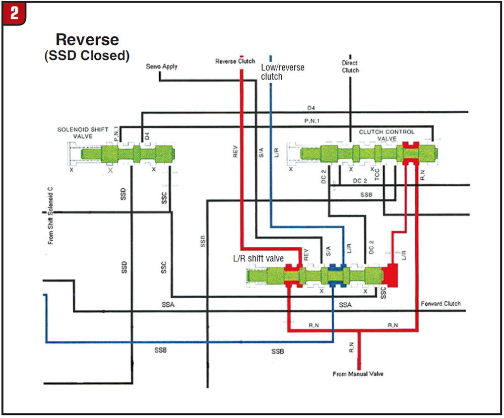
It is time to revisit the oil-circuit diagram. One of the first things we see is that line pressure from the manual valve flows through the clutch control valve to shift the low/reverse shift valve to the reverse position. This allows line pressure to flow to the reverse clutch and SSB pressure to the low/reverse clutch. So let’s see what happens if shift solenoid D (SSD) is stuck open (Figure 3). SSD pressure will stroke the clutch control valve, thus cutting off line pressure to the low/reverse shift valve.

With the low/reverse shift valve in the forward position, no pressure will reach either the low/reverse or the reverse clutch and we have no reverse. So far so good, but SSD is on in Park, Neutral, 4th and 5th gears, and we said earlier that the unit had all the upshifts. If SSD is the problem the question becomes how we can have all the upshifts with SSD on when it is supposed to be off.

For first and second gears it is easy. There is no line or solenoid pressure to the clutch control valve so its position doesn’t matter.
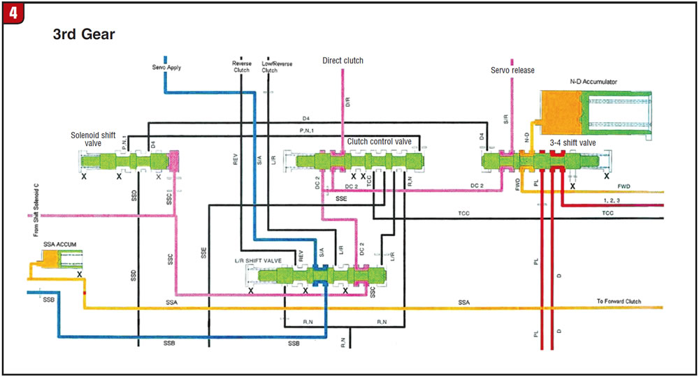
If you look at the oil circuit for 3rd gear (Figure 4) you can get an idea of what happens in 3rd and 4th gears. In 3rd gear, shift solenoid C (SSC) is turned off, sending solenoid pressure to the solenoid shift valve, 2-4 servo release and the 3-4 clutch. When the solenoid shift valve strokes, it routes pressure from the stuck-open SSD to the 3-4 shift valve instead of the low/reverse and clutch control valves; this, in turn, allows the 2-4 servo apply and 3-4 clutch pressure to flow normally. When SSD pressure strokes the 3-4 shift valve, shift solenoid A (SSA) pressure (forward clutch) will flow to the release side of the servo and the unit will shift to third. Finally, SSA turns on, cutting off forward-clutch and servo-release pressure and the unit shifts to fourth. The primary valve body has done its job and has no effect on the 4-5 upshift. This is all done in the secondary valve body.
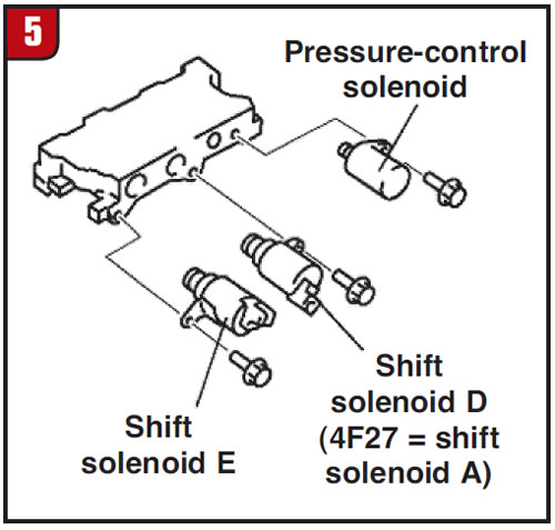
If you run into this problem on an FNR5 it is easy enough to check. You can swap SSD and SSE around and see whether you get reverse or blow air through the snout of SSD. If you can blow past the checkball you have found the culprit. The same thing can happen on the four-speed version of this transmission. Just remember that if you run into this on a 4F27E, Ford labels the solenoids differently (Figure 5).
Seems a little bizarre but there you have it, a reverse concern caused by a solenoid that at first glance doesn’t have much to do with it.
Joe Cangelosi provides product support to retail rebuilders via the VBX support line.