Understanding lube flow control valves in Toyota/Lexus UA/UB80 transmissions - Transmission Digest

Understanding lube flow control valves in Toyota/Lexus UA/UB80 transmissions

The Toyota/Lexus UA80 and UB80 transmissions first came out in 2017 in Highlanders and Siennas. The UA80 is used in V6 applications, and the UB80 is paired with four-cylinder versions. They have been called Toyota New Global Architecture type transmissions, and alternately referred to as the “Direct Shift 8AT” eight-speed automatic transmission. This transmission was produced to replace the previous-design U880F eight-speed and the U660/760 units to provide improved performance and efficiency.

These units are unique in several ways, and there are a couple of things that immediately stand out about this transmission. The first is the fact that the torque converter has moved away from the two-path design to a three-path design. This makes the TCC apply a separate clutch pack and piston inside of the torque converter and can provide better control when in “flex” or partial TCC apply. This new-design torque converter helps eliminate the TCC shudder issue when in partial apply—a problem that plagued the U660/760 transmissions.

The second item that makes this transmission unique is that it incorporates a new valve design. This valve is in the cooler return and lube circuits. There were no OE breakdowns of the valve body at the time Sonnax began researching the UA80 and UB80. Based solely on its function, we named it the “lube flow control valve,” or LFC valve for short. The LFC valve is in the middle valve body just below the pressure regulator valve.

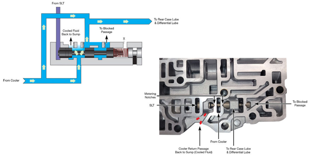
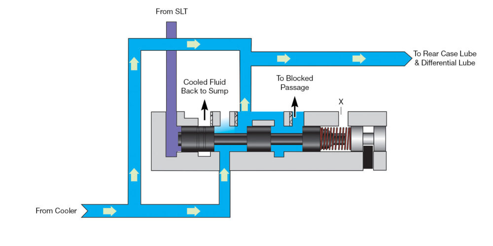
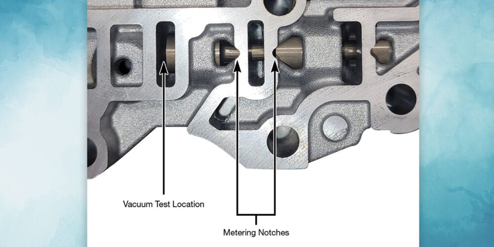
At first look, the metering notches were very interesting; I have never seen something like that before. The process of reverse engineering the oil circuit uncovered the need for the metering notches and showed why they were put there. Figure 1 (above) shows a partial circuit diagram of the LFC valve and the circuits connected to it, as well as their locations in the valve body casting. Notice that the metering notches are there to provide connections to both the rear case and differential lube circuit, as well as the circuit that connects cooler return oil to the sump in most positions of the LFC valve. 

Also, notice that the LFC valve is controlled by SLT pressure. The SLT circuit is also connected to the pressure regulator valve. This is a very active circuit, as it is constantly adjusting line pressure to match engine load. A closer look at the LFC valve circuit and the different positions can be found in Figures 2 and 3. 

Figure 2 shows the LFC valve in a position during normal-to-lower line pressure. The valve is positioned more to the left, which directs cooler return oil to the rear case and differential lube circuits. It also makes a connection through the valve’s position back to the sump, which cools transmission fluid.

Tasc-Tip-December-Figure-2---Normal-to-Lower-Line-Pressure-LFCV-Position-1400
Figure 2.

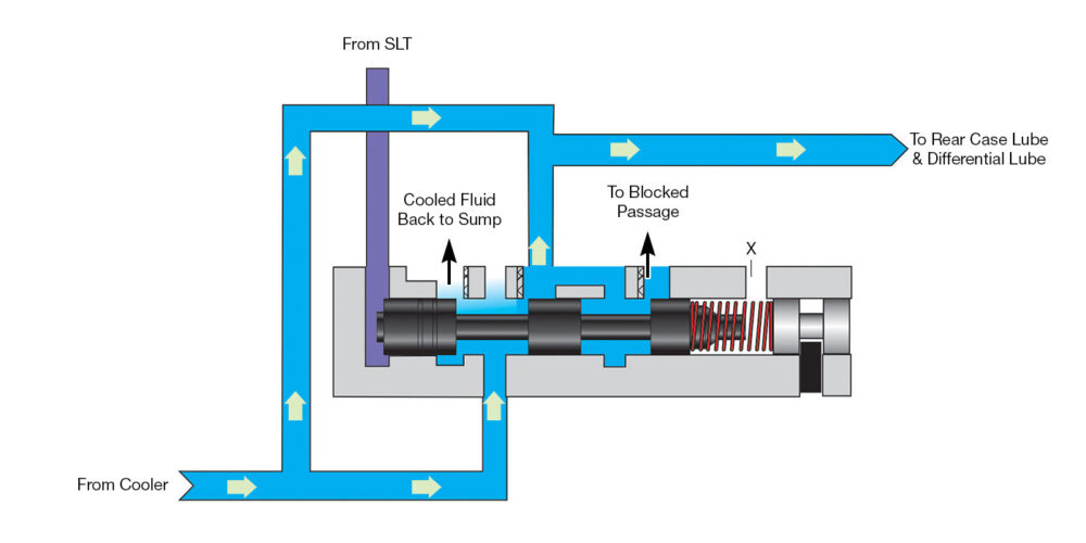
During higher loads and higher line pressure, the LFC valve is positioned more to the right by higher SLT pressure. This directs cooler return oil to the rear case and differential lube circuits, but limits the connection from the cooler back to the sump (see Figure 3).

Tasc-Tip-December-Figure-3---Medium-to-High-Line-Pressure-LFCV-Position-1400
Figure 3.

In summary, this valve prioritizes lube flow to the rear case and differential most of the time and should be checked any time you are rebuilding these transmissions, especially when there is fluid overheat, drivetrain failures or unexplained clutch or brake failures.

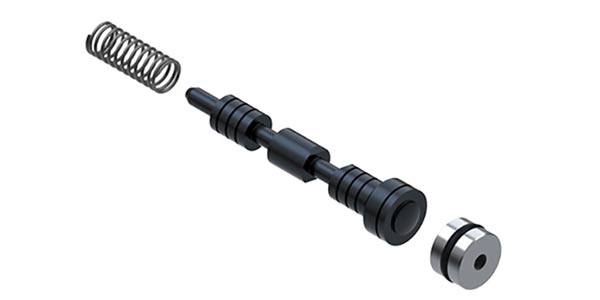
This new-design valve has already shown signs of significant wear. The port where the SLT circuit is fed is the best location to vacuum test the valve (see Figure 4).

Tasc-Tip-December-Figure-4---LFC-Valve-in-Middle-Valve-Body-Casting-1400
Figure 4.

The complaints related to a worn bore for this valve would be: transmission fluid overheat, lube failure, planetary damage and even no line pressure rise, as the SLT circuit could be directed to the sump.

Read more stories from our TASC Force Tips series here.

Jim Dial is a Sonnax technical specialist. He is a member of the Sonnax TASC Force, a group of recognized industry technical specialists, transmission rebuilders and Sonnax technicians.

You May Also Like

A guide to common GM, Ford and Nissan programming issues

One of the most common complaints I hear from shops when trying to install a new GM TCM is, “The module will not communicate.” While that might be partially true, by design they won’t communicate until they are programmed. If programming fails, there will be an “E” code set which will help you get to

One of the most common complaints I hear from shops when trying to install a new GM TCM is, “The module will not communicate.” While that might be partially true, by design they won’t communicate until they are programmed. If programming fails, there will be an “E” code set which will help you get to the root of your problem.

Shift of the shaft: Diagnosing Chrysler 48RE manual shaft issues

The TorqueFlite transmission has been around since mid-to-late 1950s. There have been many changes surrounding the manual shaft and rooster comb through the years. This transmission shaft controls the position of the manual valve that directs oil for the gear ranges, but it also is used for a Reverse light control as well as Park/Neutral

Sometimes, a diagnostic code is all you need

With ATSG having the opportunity to help shops solve problems, sometimes we get faced with some real doozies. A shop will call and give us a laundry list of DTCs, leaving us to think someone must have a bulkhead connector unplugged. We then go through the arduous task of deciding which codes prompted other codes

10L80 and 10R80 pump gear differences

You may have seen an article in the August 2023 issue of Transmission Digest called “GM 10L80: A new kind of pump noise,” which goes over how the front cover housing in the 10L80 is fitted with a converter drive gear and idler gear. The idler gear drives the pump’s driven gear, and is press

Shift Pointers: What to do when the 62TE TRS tab breaks

How frustrating it is when on a hot summer day, as you go to open a nice cold can of your drink of choice, and the tab breaks off? You are outside, away from any tools to remedy the problem quickly. It now requires a MacGyver mentality looking around at the resources available to get

Other Posts

Sonnax introduces GM 6L80, 6L90 output planet saver kits

Sonnax has introduced new output planet saver kits for GM 6L80 and 6L90 transmissions. The company says these kits can repair and prevent common concerns and save the planetary assembly when installed. Related Articles – Transtar to offer recycled engines – Alto introduces filters for GM 6L series – PRT launches 30 new complete strut

Sonnax introduces Smart-Tech clutch kit for GM 4L series

Sonnax has introduced a new Smart-Tech clutch kit for optimizing clutch capacity and guarding against clutch burnup in GM 4L60, 4L60-E, 4L65-E and 4L70-E transmissions. This kit (part no. 77734-01K) includes eight .067-in. BorgWarner high-energy frictions and seven .095-in. Lindered steels recommended for use with Sonnax Smart-Tech input housings. Related Articles – Force Control Industries

Sonnax introduces oversized low reverse/overdrive clutch regulator valve kit

Sonnax has introduced a new oversized low reverse/overdrive (4-5-6) clutch regulator valve kit (part no. 144740-43K) for Ford 6F35 transmissions, generations one, two and three. Related Articles – American Powertrain introduces ProTwin disc clutch for GM, Ford and Mopar – Snap-on debuts new general service tool set  – Gray Tools introduces insulated hex bit socket

Sonnax introduces heavy-duty ‘A’ clutch backing plate

Sonnax has introduced a new heavy duty “A” clutch backing plate (part no. 35577-45) for Chrysler 845RE and 850RE, and ZF 8HP45, 8HP50 and 8HP51 transmissions. Sonnax says that this plate can eliminate the flexing/bowing of the clutch pack that leads to comebacks in these transmissions, and recommends installing them in units that have not