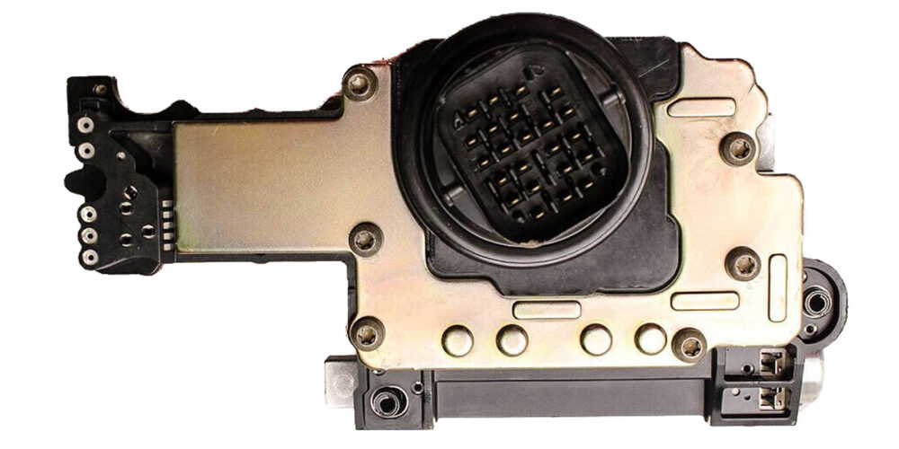
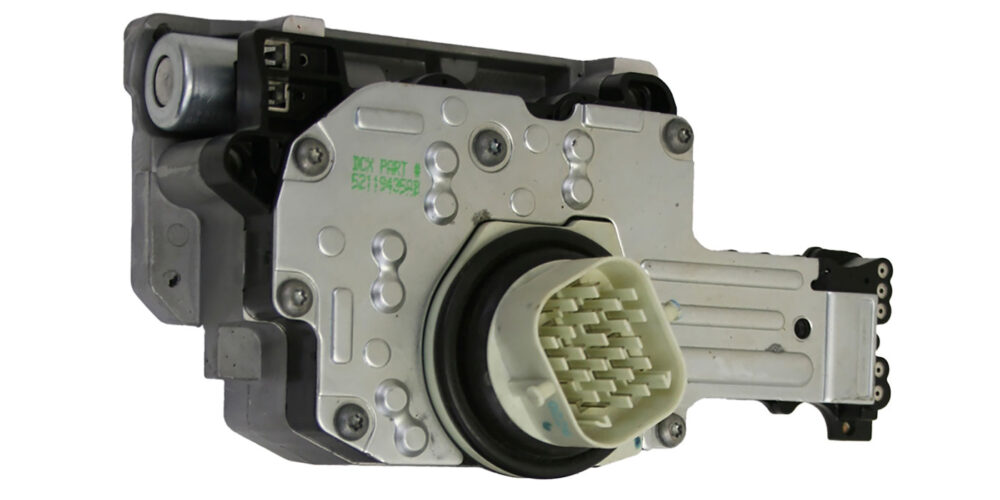
The Chrysler 68RFE has had several changes through the years. Its four-speed predecessor began with a noisy solenoid pack identified by a black colored pass-through case connector (seen in Figure 1).
In 2004, they changed to a quieter design assembly identified by a white pass-through connector (Figure 2).
This is used in all 45RFE and 545RFE transmissions and it is what the 68RFE began with. By 2010, the 68RFE underwent some running valve body changes which included eliminating the overdrive solenoid (Figures 3 and 4).
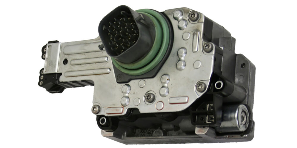
This solenoid assembly is identified by a gray pass-through case connector (Figure 5).
In 2019, a major change occurred by adding to the lower channel plate a small housing assembly that contains a TCC solenoid which is separate from the solenoid assembly (Figure 6).
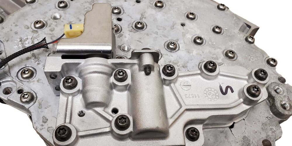
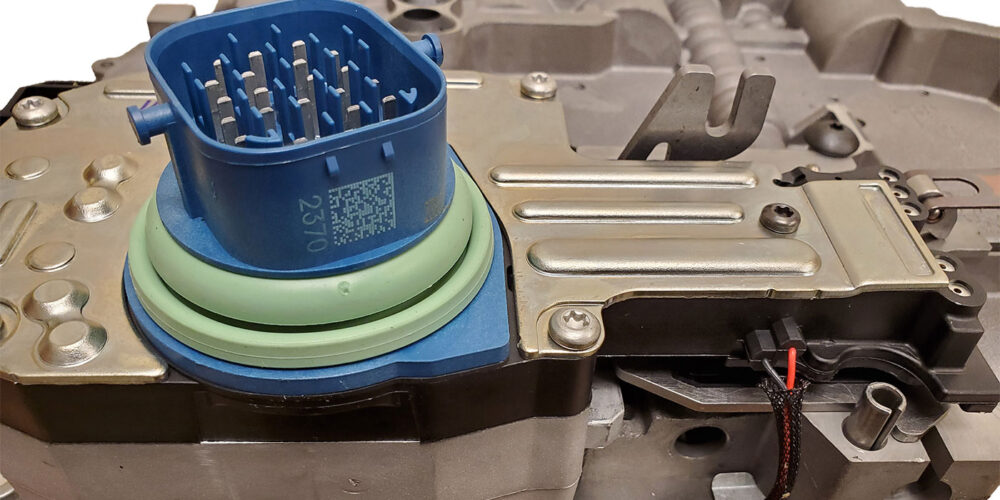
The L/R solenoid is now used to apply the L/R Clutch in Park, Neutral and Drive first gear; it no longer doubles as a TCC Solenoid. For quick identification of this change, the pass-through connector is now blue in color (as seen in Figure 7).
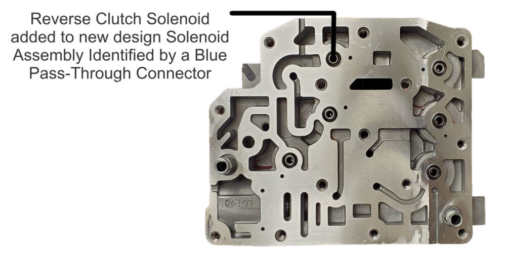
Aside from adding a separate TCC solenoid as seen in Figure 6, they added another solenoid to the assembly that never existed in any previous RFE units: a Normally Applied Reverse clutch solenoid, which is conveniently located where the OD solenoid used to be (see Figure 8).
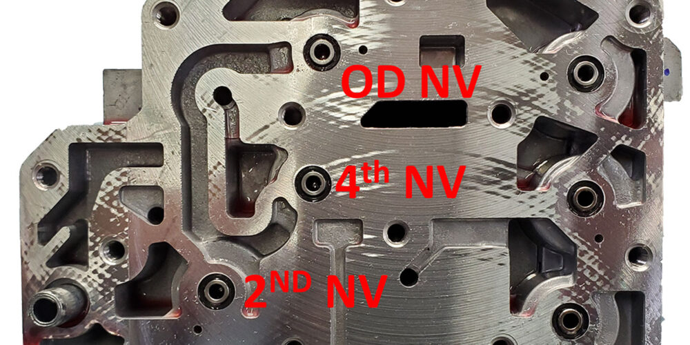
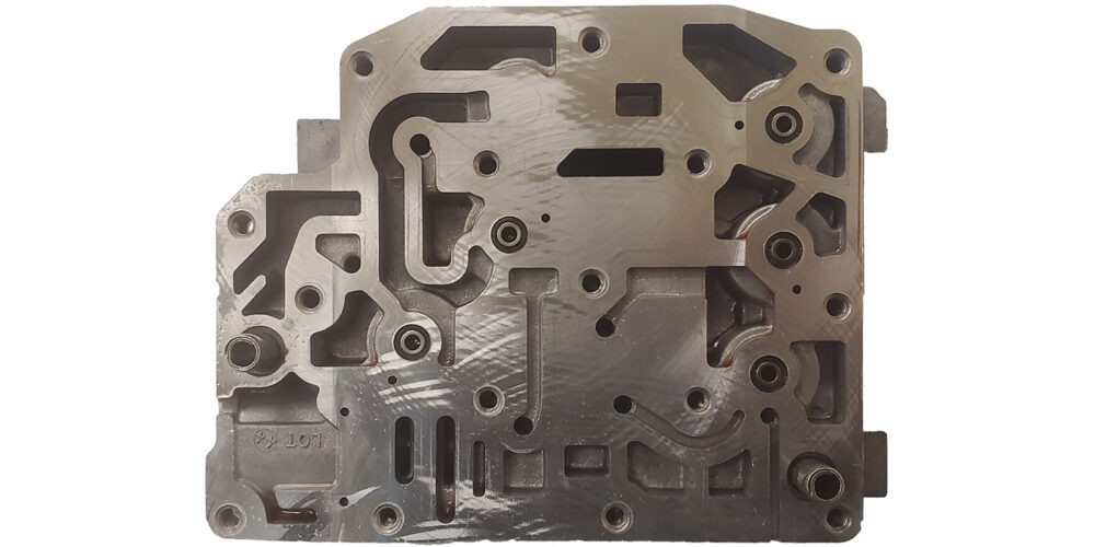
This means there are now two different silicone beaded solenoid block gaskets in circulation. Figure 9 shows the gasket used on the gray and white solenoid connector assemblies, while Figure 10 shows the gasket used with the blue solenoid connector assembly.
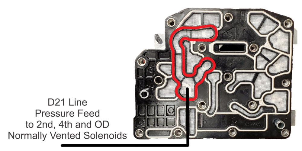
The call-outs in these two figures show the feed circuits to these solenoids. In Figure 9, the red outline shows the D21 Line pressure feed passage supplying pressure to the normally vented second, fourth, and OD solenoid. The same gasket is used with the gray solenoid assembly that eliminated the OD solenoid (back in Figure 4). With these solenoids normally being the vented type, they need to be energized to apply their respective clutch.
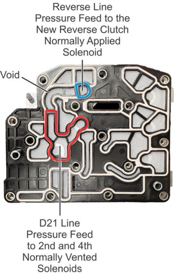
After placing a Reverse solenoid in the previous OD solenoid location, the gasket changed to accommodate this new solenoid. In Figure 10, the red outline shows how the D21 Line Pressure feed is routed to the second and fourth clutch solenoids only. The blue outline shows how the feed to this Reverse Clutch solenoid is isolated from the D21 feed circuit with a void pocket in between.
These differences mean that by using the wrong gasket, you could have either a bind-up going forward or a neutralizing 2-3 shift. The explanation is as follows:
- If the gasket seen in Figure 9 is used on the blue solenoid connector assembly, this will allow D21 line pressure to be fed to the Normally Applied Reverse Clutch Solenoid when the selector lever is placed into Drive. The result will be a bind up as soon as the brakes are released to move forward.
- If the late gasket is used on a white connector solenoid assembly, feed to the OD solenoid will be blocked. With no D21 line pressure feeding the OD solenoid, it will cause a neutral shift into third gear. It will still have third gear failsafe as the multi-select solenoid is used to apply the OD clutch in this mode.
Obviously, it is best not to make this mistake in the first place; but as we know, these things can easily happen on a busy day. In any case, it is good to know these symptoms when making this mistake so you can quickly identify what is causing the problem, avoiding needless hours trying to figure it out.
Read more stories from our Technically Speaking column series here.