The subject of this article is a 2002 Ford Ranger with a 3.0L V6 engine and 5R44E transmission. There were 191,622 miles on the vehicle when it arrived at our shop. The owner said that the transmission was not shifting correctly and the OD lamp was flashing.
I performed the initial evaluation and road test, then scanned for any DTCs that were recorded. There was a series of ratio codes: P0731 (ratio error in first), P0733 (ratio error in third), P0734 (ratio error in fourth), and P0735 (ratio error stored in fifth). On my road test I experienced erratic shifting and there were flares (spin up) between shifts. The transmission fluid was in very poor condition and had a burnt odor to it. I also checked the battery and charging system. I found the alternator had AC ripple out of range (too high). The alternator was replaced and retested, and the ripple issue was corrected.
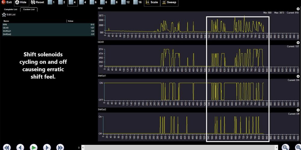
A replacement remanufactured transmission was recommended. The customer authorized the repairs, and we installed the transmission. However, during the final road test, the transmission started to shift erratically. The scanner data indicated that the solenoids were being cycled on and off. A movie of the road test was captured and analyzed once the vehicle was back at the shop. (See Figure 1.)
After reviewing all the data, I concluded that there was a fault with the PCM. I could not find anything commanding the erratic shifts. I did a static test of the powers and grounds and all tested well. We let the customer know, and we installed and programmed a used replacement PCM and reset the PATS (passive anti-theft system). After an extended final road test, the vehicle was working properly and was delivered to the customer.
Our customer put about 190 miles on the Ranger, then returned to the shop, this time saying that the OD lamp was flashing and transmission was not shifting correctly. He said that it had to be driven 30-plus continuous miles before the lamp starts flashing. It seemed rather odd for it to take 30-plus continuous miles for the transmission to set a DTC. Regardless, we were back to square one.
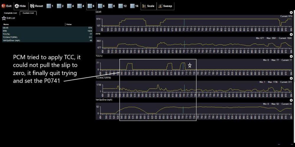
I started down the highway and kept the vehicle at a steady speed. At mile 32, the torque converter clutch started slipping and code P0741 (TCC system, mechanical problem) set, and the OD lamp started flashing (See Figure 2).
I decided to get off the highway at that point, and when I did, the transmission would barely pull itself and was slipping through every shift. I had to nurse it back to the workshop. I wasn’t sure I would make it without a tow.
The condition of the transmission had deteriorated so much that a replacement transmission had to be installed. The replacement transmission was not working much better, and it didn’t take long before the transmission began to shift oddly. When coming to a stop, it would go from fifth to first, and then taking off, it would shift first to fifth. There was no upshift to the next gear, and when slowing there was no downshifting to the next lower gear.
There had to be something wrong with this vehicle to set DTCs, cause erratic shifts and slip. I decided that a deep dive into this vehicle was required. I started with a line pressure and EPC pressure test. The actual gauge pressures were compared to the information on the scan tool.
The EPC pressure was much lower than what the scan tool was showing.
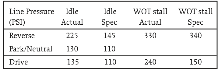
Since the EPC pressures did not match the scan tool data, I suspected that the used PCM I purchased was faulty. That’s the unfortunate risk we take when sourcing used controllers.
I replaced the PCM again, reprogramming and resetting PATS. The pressures were tested again, and this time the EPC pressures aligned with the scan tool data. The line pressures read near the specification. But it was too late for this transmission. I had driven it long enough to do damage to the clutches and bands. I replaced the transmission again.
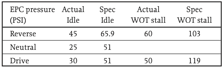
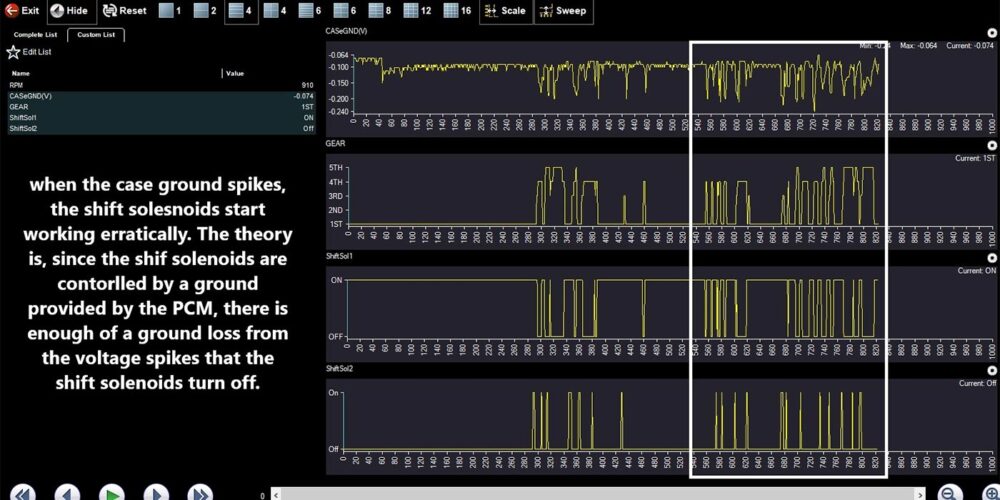
On the road test for this new transmission, I noticed shift solenoids being commanded erratically and the DTCs returned almost immediately. A movie was taken of the road test and reviewed once I got back to the shop. Since I did not know what I needed to look at on the data PIDs, I kept all the PIDs available to capture. I could eliminate the PIDs I didn’t need and narrow the list down later. I found that when the case ground data PID went out of range (0.250 volts), the DTCs would set.
Take a look at Figure 3; that is a lot of voltage on a ground circuit. Looking at the case ground on the scan tool was not something I paid a lot of attention to, until now.
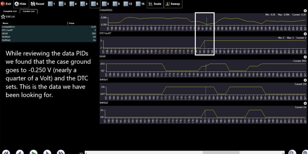
In addition, matching the erratic case ground event to the cycling shift solenoids’ timing, I had some ammunition and a direction to go (See Figure 4).
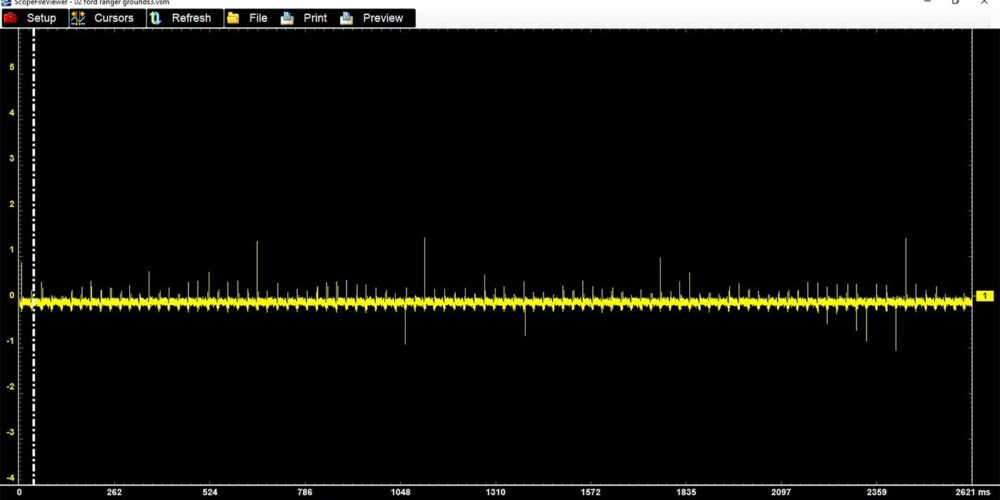
I scoped four out of the five grounds at the PCM. I was shocked to see the voltage on the grounds randomly spike as high as four volts. (See Figure 5).
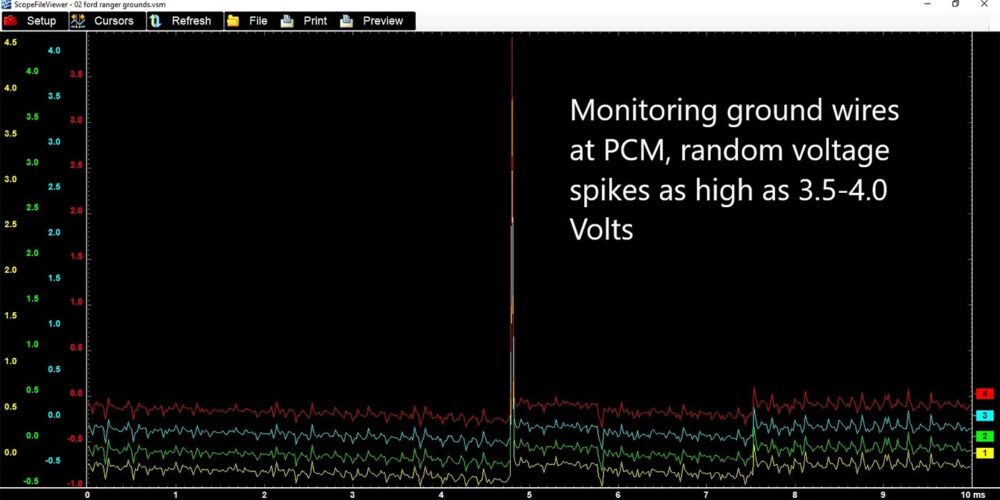
These spikes had no pattern and were very random. Since there are five separate grounds that spliced into one, I decided that I would make a jumper harness from an old Ford PCM harness so that I could bypass them for testing.
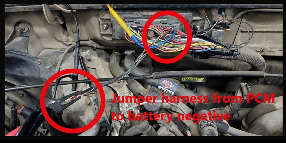
The five grounds at the PCM (pins 24, 51, 76, 77, 103) splice into a 10-gauge wire that goes under the intake plenum and into a bulkhead connector (C124), then to G108 at the radiator support. I suspected there was an issue with the C124 connector. The jumper harness would eliminate any issues along the way. I repinned the PCM connector with the jumper harness I’d made and ran straight to the battery negative terminal (See Figure 6).
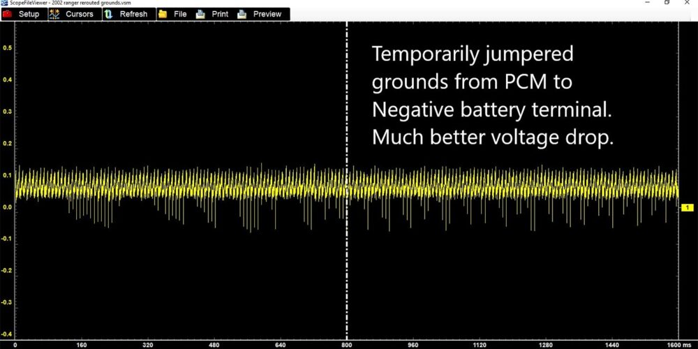
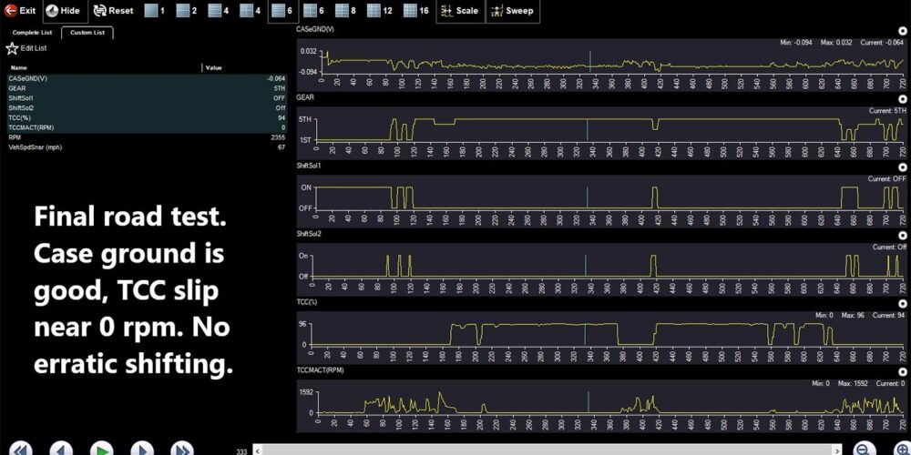
The scope pattern idling with all the accessories on looked much better. Even though there was some noise on the circuit, the average voltage was less than 0.1 volt (jumper wire and alligator clips). This road test went very well. No longer were there voltage spikes on the ground circuit; the shifts were smooth and on time; and the TCC slip was zero RPM. Take a look at Figure 7; it appeared that I’d found the problem.
After returning from the road test, the jumper harness was made permanent. A 10-gauge wire was soldered onto the splice and a new crimp-type battery terminal was installed on the negative battery terminal. Once the harness was permanent and routed nicely, the Ranger was driven several more times for long distances. The scope pattern for the ground now was 0.025V to 0.07V. The Ranger was ready to give back to the customer. (Figures 8 and 9).
Hindsight is always 20/20 and looking back, the static voltage drop test with a DVOM on the ground was not enough to see these random spikes. I don’t always look at the ground PID on the scan data, so that was initially missed. Going forward, voltage and ground PIDs will be a part of data I look at going forward. This is how we learn to enhance the accuracy of our diagnoses.
Read more stories in our R&R Tech series here.
Brent Brown is a diagnostician at Certified Transmission’s shop in Gladstone, Missouri. When not diagnosing transmission problems on cars and trucks, one will likely find Brent spending time with his wife, three sons, and daughter. Brent enjoys reading and sketching in his free time along with tending to his Bonsai trees.