Let’s take a look at three examples of times when a car’s issue seems to be a transmission problem, but a closer look reveals another culprit.
Case study 1: Ford 5R44E
A 2009 Ford Ranger 2WD 2.3L with a 5R44E transmission and 110,000 miles on the odometer comes to the shop with a concern of intermittent overdrive cancel light flashing and coming out of overdrive.
When the truck is scanned, there are no fault codes retrieved; the only code stored is a P1000 indicating that codes haven’t been cleared by the previous shop that attempted to repair this vehicle. A quick test drive of the vehicle confirmed that the transmission would randomly shift in and out of overdrive as the customer described. The customer shared that the previous shop purchased and installed a new gear box assembly. This attempted repair was unsuccessful, so the next solution was to unplug the transmission control switch, which solved the “light” issue but did nothing for the random downshifting.
Now it is time to dig a little deeper.
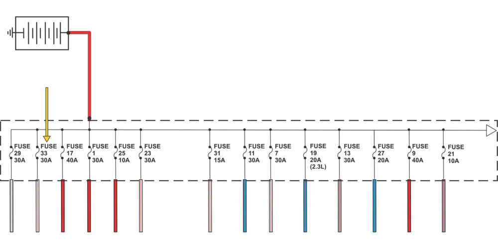
First, an understanding of how this part of the system is in order. If you look at the simplified illustration of the wiring diagram (as seen in Figure 1), you will find that transmission control switch is provided with system voltage provided through the yellow/violet wire by fuse 20, a 10-amp fuse in the battery junction box that is only hot in the run position of the ignition switch. When the transmission control switch is depressed (this is a momentary switch that only makes a connection when held in (like a doorbell), the system voltage is then sent through the brown/green wire to the PCM, signaling for the PCM to inhibit or cancel overdrive.
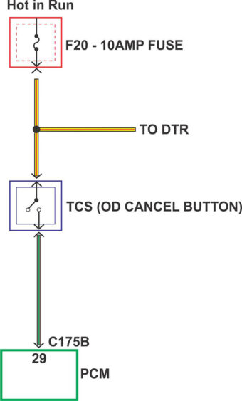
Now we need to check for power on the yellow/violet wire. At this time, battery voltage is found on this circuit only with the key in the run position. Ok, so far so good. Now let’s check the brown/green wire. Uh-oh; we have a week voltage signal that fluctuates with the key off or in the run position. Let’s go a little further down the path and check at the PCM for voltage on pin 29 in connector C175B (as seen in Figure 1). With the connector unplugged and the brown/green wire back probed, the same erratic voltage reading is discovered, whether the key is on or off.
This is an important clue. The voltage on this side of the connector would explain why the computer would cancel overdrive with the transmission control switch unplugged. Where can this “at all times” voltage be coming from?
A closer look at the battery junction box diagram shows that there are multiple circuits that are always hot (see Figure 2). The technicians decide to pull fuses one at a time until the brown/green wire goes dead. When fuse 33 (which is a 30-amp fuse) was pulled, the circuit goes dead.
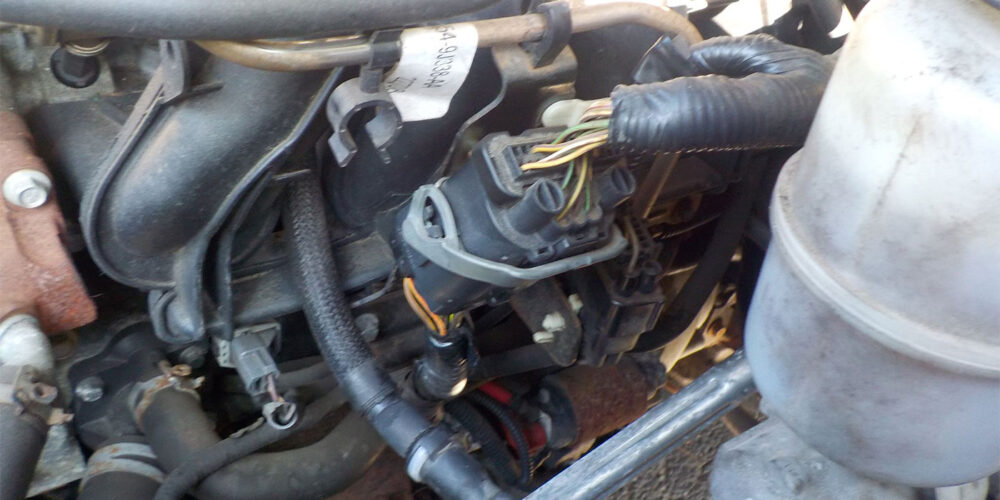
A tracing of the wire powered by this fuse leads to connector C110, which is secured to a metal bracket on the composite-made intake manifold (see Figure 3). This is one of the few places a wire can be chaffed without shorting or blowing a fuse.
A close look at the images shows both the brown/green wire and the white/red wires rubbed through the insulation (see Figure 4), exposing the wire inside and completing the connection between the two wires.
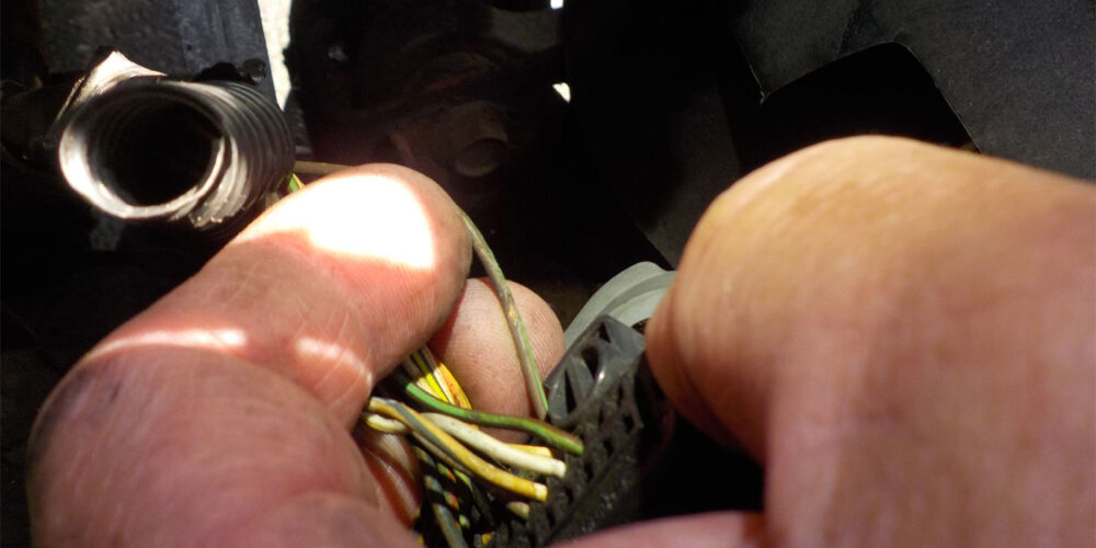
This intermittent connection led the PCM to believe that the diver was signaling for overdrive to be cancelled. A quick fix of the two wires along with relocating the connector to avoid contact with the bracket was involved to confirm the fix.
Case study 2: Dodge Caravan with 604 transmission
A 2003 Dodge Caravan Sport with 3.3L engine, 604 transmission and 145,000 miles driven arrives at the shop with a concern of surging, jumping and the speedometer going up when it is at a stop. Codes recorded on arrival are:
- P0622 generator field not switching properly (an important clue)
- P1790 fault immediately after shift
- P0720 output speed sensor error
A previous shop referred the customer to us for a transmission diagnosis. A quick road test revealed erratic shifting, erratic speedometer operation and going to failsafe. A generator whine (another important clue) was also noted.
Based on this information, technicians decided to pursue the generator. When the vehicle was brought into the shop and parked in the bay, technicians noticed that the battery was recently replaced. A check of charging system voltage shows a proper DC voltage. But when AC voltage is measured, a reading at the battery was recorded at over 300MV, which is more than allowable. At this time technicians unplugged the generator field harness connector with the engine not running. This is done to inhibit charging when the engine is restarted. When it was restarted, the DC voltage was at battery voltage, and the AC voltage was now gone. A test drive confirmed proper operation.
With the generator unplugged, the van exhibited normal shifting with no more speedometer errors. We recommended that the customer return to his original shop for generator diagnosis and possible replacement. The original shop determined that the generator was not the problem and referred him back to our shop.
At this time, with the customer’s approval, we ordered and installed a remanufactured generator from the local auto parts store. The repair was confirmed with a follow-up test drive and a scan for codes, which showed no system faults. After a few weeks, we gave the customer a courtesy call to confirm that the van was working properly; we received positive feedback and thanks for an accurate repair.
Case study 3: 2009 Nissan Rogue
A 2009 Nissan Rogue S with a 2.5L engine, TRANSMISSION and 62,932 miles driven arrived at the shop, with the customer saying that id does not have first gear, has no throttle response, followed by a sudden engagement which resulted in going into failsafe. Time for a transmission, right? It is a CVT after all.
Time to take a closer look before we sell a transmission by scanning this vehicle. The codes retrieved were as follows.
- P0703 Brake Switch B (found in TCM)
- C1116 Stop Lamp Switch (found in ABS module)
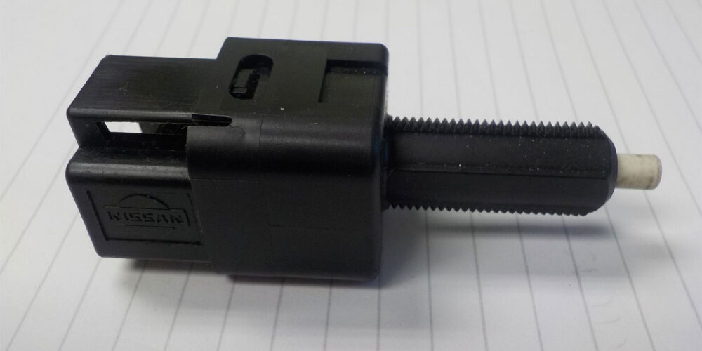
The switch referenced in P0703 is the brake switch (stop lamp switch), mounted on the brake pedal bracket (see Figure 5). It will be the connector E115 with four wires, not to be confused with the cruise control (ASCD) E112 connector.
The E115 switch is used to send a signal to the ECM when the brakes are applied so a series of actions can be taken. The most relevant of these to our situation is that the computer will limit the amount of throttle given as this vehicle (as well as most of the cars on the road today) is drive-by-wire. The gas pedal is only an accelerator pedal position sensor and is not connected directly to the throttle body. With the brake pedal applied, the computer “kills” the throttle the same way it does when you are stuck in the snow, or when the traction control takes over, so you don’t dig yourself a deep hole when stuck.
Now to drive the vehicle. Taking off from a stop is fine unless you are in a hurry. If you are light on the throttle, the car almost drives normally. If you get into the throttle, the computer takes control and limits your throttle thus limiting power. The car can make it to highway speed if you are patient and the transmission appears to be performing normally. So, let’s now look for the brake switch PID in the scanner. There we find that the switch is showing the equivalent of stepping on the brake pedal while driving the vehicle. The computer sees this and responds by limiting the throttle given to the engine, creating the circumstances the customer has experienced.
A quick check of the switch shows the plunger is only coming out halfway. If it is pulled out the remainder of the way, the scanner reveals the correct values returning throttle control back over to the driver. With this information, a decision was made to replace the switch and perform a final road test to confirm a successful repair.
Read more columns from our Shift Pointers series here.
Special thanks to Robert Pleasanton of Automotive Diagnostic Solutions for some of the electrical diagnostics in this article. The help of a good mobile electrical system diagnostician / programming person is a keystone to successful automotive repairs. Diagrams were provided by Wayne Colonna.