P1870 Revisited - Transmission Digest

P1870 Revisited

Just when you thought you had all the P1870 torque-converter-clutch slip codes under your belt, another vehicle comes along – and here we go again!

P1870 Revisited

Shift Pointers

Author: Jim Dial, ATSG Senior Technical Consultant

Shift Pointers

  • Author: Jim Dial, ATSG Senior Technical Consultant

Just when you thought you had all the P1870 torque-converter-clutch slip codes under your belt, another vehicle comes along – and here we go again!

I am sure that most of you are familiar with the 4L60-E P1870 TCC-slip code and torque-converter-shudder problems related to the code. This usually is related to wear-out of the torque-converter regulator-valve bore causing a loss of torque-converter apply pressure, allowing the TCC to slip, and we all know what fixes are available for that.

Now we have 2000 Isuzu Trooper and BMW models equipped with the 4L30-E transmission showing up in shops with the same P1870 code. You guessed it – the same kind of TCC regulator-valve-bore wear is the cause here also. The biggest problem is that there is little printed material to tell us where the TCC regulator-valve train is and how it works. We all know that if you don’t know how it works, you can’t even begin to fix it!

History: In the 2000 model year, Isuzu Trooper and some BMW models went to a pulse-width-modulated (PWM) TCC apply strategy. Isuzu Rodeo, Honda Passport and Cadillac Catera stayed with the typical on-off TCC apply that they have had since day one. This strategy change, on these limited models, has created some serious confusion in parts interchange and the identification of parts.

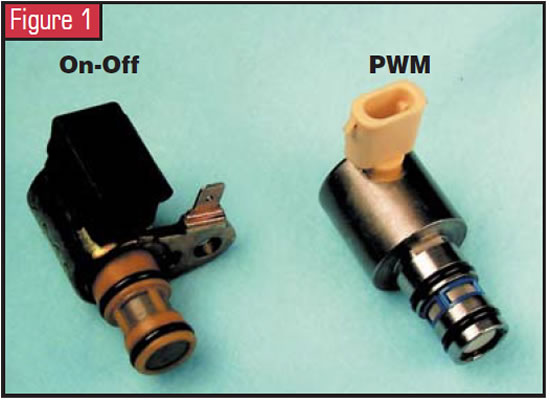
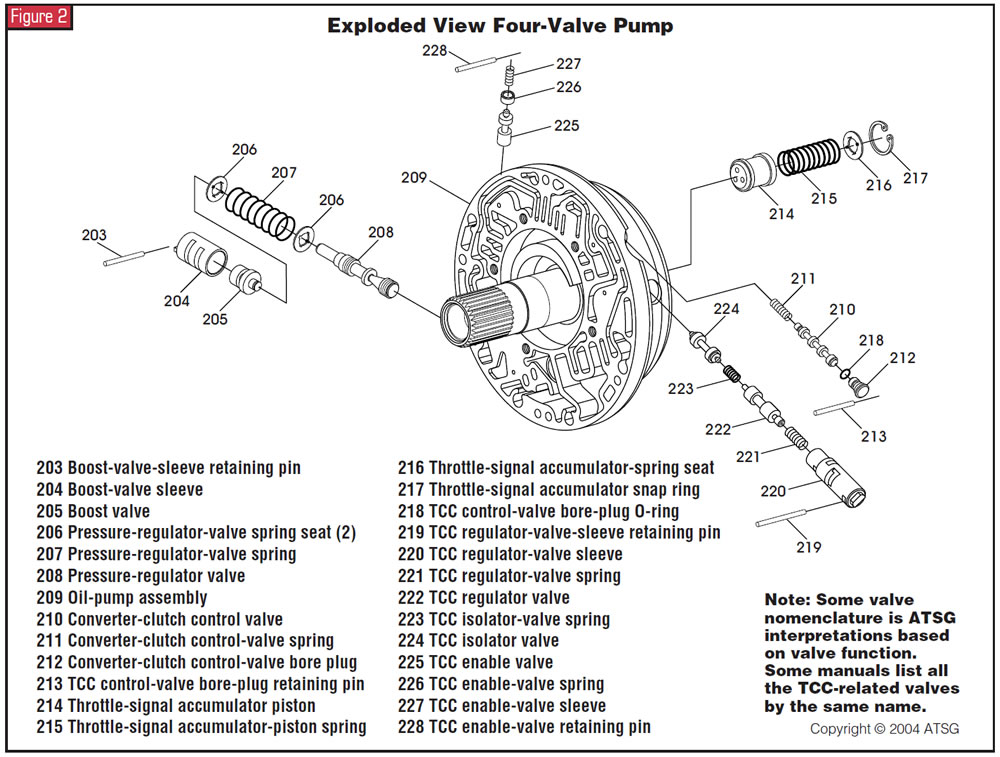
Parts change: In production for the 2000 model year, Isuzu Trooper and BMW models received the PWM TCC apply strategy. This created the need for a PWM solenoid, which happens to be the same as the 4L80-E PWM solenoid (see Figure 1). This, of course, changed the internal wiring harness because of the connector change. The pump changed from having two valves to four valves. The additional valve trains are the torque-converter regulator valve and the torque-converter enable valve (see Figure 2). Special note: ATSG has named these two valves on the basis of valve function. If you happen to find a factory manual that names them something else, don’t be confused. The torque-converter control valve also changed and now has a bore plug with an O-ring. The pump plate and bellhousing also changed because of the valve additions, and, of course the TCC went to a high-carbon or woven type.

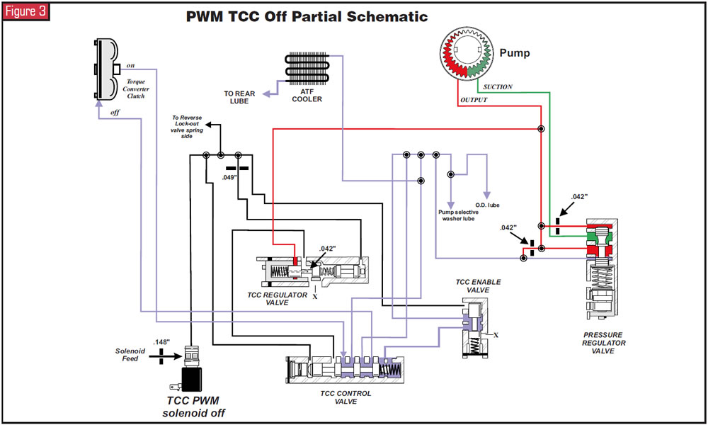
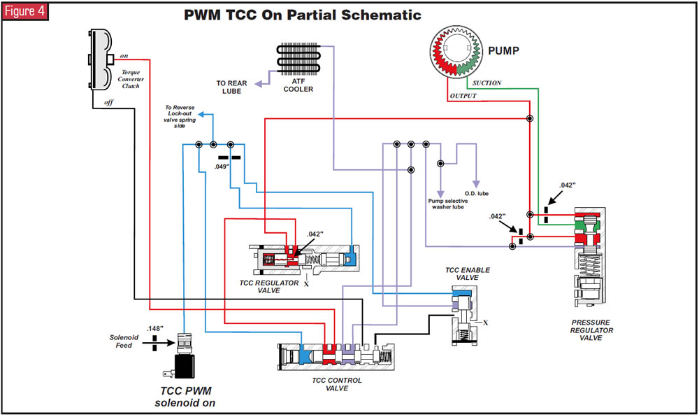
The point: The main focus of this article is to show how it works. No known hydraulic-circuit diagrams have been available for the PWM TCC apply, so I decided to fix that. Refer to Figure 3 for a partial hydraulic-circuit diagram of the TCC off. Figure 4 shows a partial schematic of the TCC when it is on. Notice that the PWM solenoid, when it is on, is in charge of stroking three valves simultaneously: the TCC control valve, which basically is the switch valve; the TCC enable valve, which controls the spring side of the TCC control valve and the exhaust path for TCC release oil; and the TCC regulator valve, through a 0.049-inch orifice in the pump plate, which controls TCC apply pressure on the basis of the spring pressure, and the balance feed through a 0.042-inch orifice, from the middle of the two lands of the TCC regulator valve (see Figure 5).

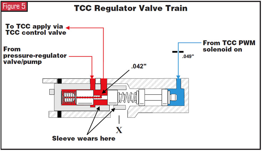
This is the root cause of the P1870. The TCC regulator-valve sleeve is what wears (see Figure 5) and creates a loss of TCC apply pressure. The great part about this sleeve is that it is sold separately from the pump and is easily replaced during overhaul for less than the cost of a fast-food lunch! The Isuzu part number for the sleeve is 8-96018-472-0, and if the valve is scored the part number for it is 8-96018-518-0.

Now you know how it works, and ATSG recommends replacement of this sleeve on every overhaul. We hope to see you in the upcoming 2005 seminar, where we will cover this problem a little more in depth, showing and comparing all the on-off and PWM changes.

Thanks to some people who really helped make this information possible: Ted at Ted’s Transmission, Alex Biliski at Santilli’s Transmission, Dynamic Dino and John Forrester.

You May Also Like

Sherlock Holmes Approach to an AB60 No-Move Situation

The effectiveness in diagnosing automatic transmission malfunctions is an art form. Although there are similarities among the wide varieties of transmissions on the road, each transmission has its own peculiarities. Aside from having mechanical, hydraulic, and electrical hardware systems to contend with, software/programming issues and various vehicle platforms make diagnostics much more difficult.  Using scopes provides

ab60

The effectiveness in diagnosing automatic transmission malfunctions is an art form. Although there are similarities among the wide varieties of transmissions on the road, each transmission has its own peculiarities. Aside from having mechanical, hydraulic, and electrical hardware systems to contend with, software/programming issues and various vehicle platforms make diagnostics much more difficult. 

GM 6T40 Pump Identification Guide

The 6T40 was introduced in 2008 for General Motors front-wheel-drive cars in the Chevrolet Malibu and has gone through several changes throughout its three generations, specifically in the pump area. The 6T40 is closely related to the more lightweight 6T30 and the heavier duty 6T45 and 6T50. Generation one started phasing out during the 2012

Seeing the Forest AND the Trees

They say that the proverbial phrase “I couldn’t see the forest for the trees” means that a person or organization cannot see the big picture because it focuses too much on the details. Related Articles – 4L60E Harsh 1-2 Shift – TASC Force Tips: Diagnosing 8L45 & 8L90 Shift Complaints – TASC Force Tips: Hydraulics

The Manifold Pipeway

The Honda six-speed transmission has been on the bench of many specialty shops for one reason or another (figure 1). But, for those of you who have yet to lay your hands on one, mounted on the upper side of the unit is one of the largest, if not the largest solenoid and pressure switch

8L90 Vacuum Testing

Below are the diagrams for vacuum testing GM 8L90 transmissions. Note: OE valves are shown in rest position and should be tested in rest position unless otherwise indicated. Test locations are pointed to with an arrow. Springs are not shown for visual clarity. A low vacuum reading indicates wear. For specific vacuum test information, refer

Other Posts

Ford 8F35 maintenance tips: Planetary failure and no-pressure conditions

Our shop has had several vehicles come in with the Ford 8F35 transmission having planetary failure. Apparently, there was a run where the pinion needle bearings had a hardness problem (see Figure 1). Related Articles – Don’t fear customer complaints about CVTs – 2024 State of the Powertrain Industry – Powertrain industry directory and buyer’s guide

Figure 12.
Shift Pointers: A Chrysler 300 no-shift complaint

The case study has to do with a 2009 Chrysler 300 C 5.7L Nag1 RWD with 71,923 miles on it (see Figure 1, above). Related Articles – A guide to common GM, Ford and Nissan programming issues – Shift of the shaft: Diagnosing Chrysler 48RE manual shaft issues – Sometimes, a diagnostic code is all

Shift Pointers: What to do when the 62TE TRS tab breaks

How frustrating it is when on a hot summer day, as you go to open a nice cold can of your drink of choice, and the tab breaks off? You are outside, away from any tools to remedy the problem quickly. It now requires a MacGyver mentality looking around at the resources available to get

Shift Pointers: Failures caused by incorrect tire sizes

For years ATSG has produced a wide range of issues related to improper tire sizes on vehicles. Even under-inflated tires have been known to cause issues. Problems such as premature failure with an active 4WD transfer case will occur with incorrect tire sizes. Related Articles – Going the extra mile: Proving your transmission repair suspicions –

Shift-Pointers-Jan-Figure-1-1400