
TASC Force Tips
- Author: Rick Hoffman
There are several ways to check valve bodies for wear: wet air tests, wiggle tests, deflection measurements, vacuum gauges or the hydraulic test stand, the last of which is the focus of this article. In our shop I needed to be able to measure the leakage accurately and record the findings before and after the repair, and be able to print the results on paper to hand to my customers.
I’ve been using a Zoom Technologies AMI hydraulic-circuit analyzer for the past two years on all transmissions before and after any repairs. This machine will find very small leaks in any circuit. But it lacks the ability to record and print the results. The hoses and operating valve are too clumsy to use on valve bodies. So it was time to modify the machine.
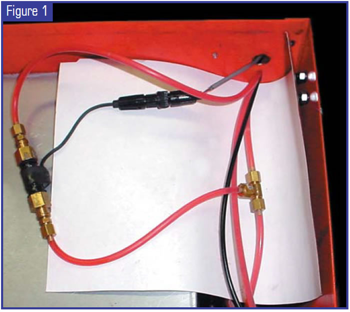
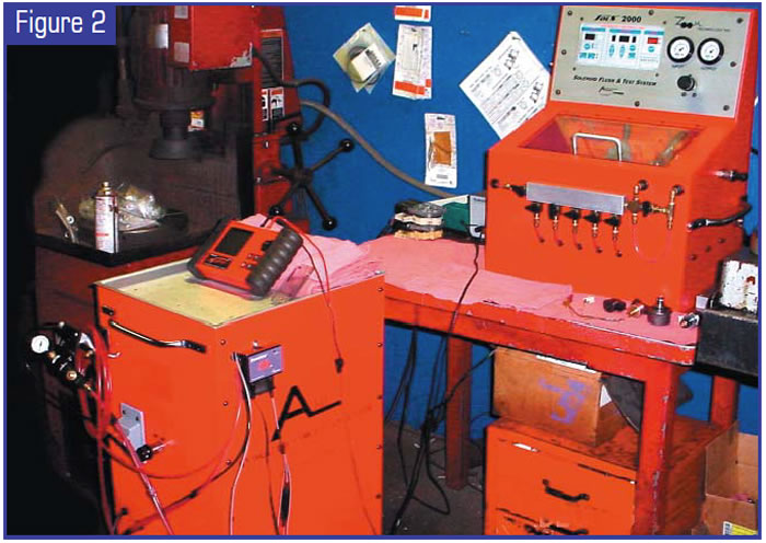
A trip to the hardware store yielded all the fittings, adapters and plastic tubing I needed to set up the following test procedures. I installed a tee fitting in the main feed line and attached a short piece of tubing to the fitting and installed a Sonnaflow™ in the line (see Figure 1). I connected a 6-inch piece of line to the Sonnaflow™ and attached a rubber-tipped blowgun to it. Then I connected the Sonnaflow™ to my Snap-On Vantage graphing meter (see Figure 2). The Sonnaflow will monitor oil flow accurately down to 0.5 milliliter per minute, so the Vantage obtains the best resolution in the graphing mode set at 50 Hz or less and the 1-second interval.
I can now read and record the flow in hertz. The flow is any leakage past a valve spool, which is isolated by the test plate. I can freeze and save the screen on the Vantage, which can be downloaded to the computer and printed for the customer.
Once this was done, I started to set a standard to check for leakage. Free flow on my machine is 2.5 Hz. A good tight circuit will read 0.4 Hz. Any circuit that flows more than 1.0 Hz is in need of a repair. Whether replacing a boost valve and sleeve or reaming a bore for an oversize valve, I can check before and after the repair to verify a fix.
An example is the 4T60-E TCC apply valve. Leakage at the largest spool will cause a no-lockup condition, even if the scan tool says TCC enable yes but the valve is not stroked. Leakage at the other lands can cause no lockup when hot, DTC 740, torque-converter shudder and burn-up of lockup plate. After repair of this complaint, a modified/closed solenoid can be installed. Pressure is applied to the TCC-signal passage and you can watch the valve stroke.
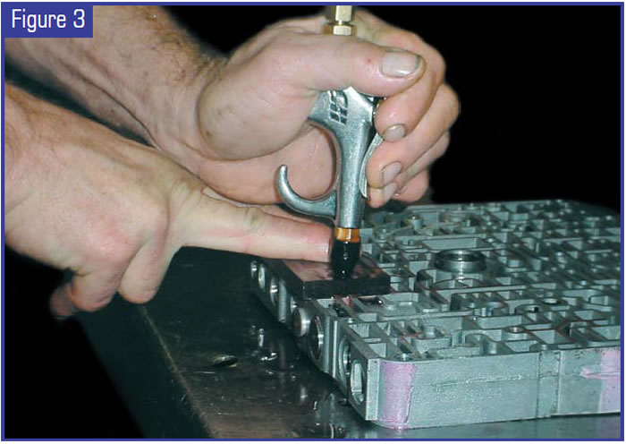
In AXODE, AODE, AX4N and CD4E units, converter shudder and reduced cooler flow can be traced to worn bypass/TCC control-valve lineups. This can be easily checked for wear by isolating and checking for leakage. Figure 3 shows a bypass clutch-control sleeve and plunger valve being tested for leakage. This bore is showing a 1.5-Hz leak. I replaced the sleeve and plunger assembly and rechecked the leakage. This unit came in with overheated planets.
In the 4L60-E, wear at the TCC regulator and the isolator valve can cause DTC 1870 codes and on later-model units can cause unit failure. This can be checked easily by isolating the circuit and checking for leakage. In 1991-94 units, isolator-valve wear will exhaust second-gear oil (see Figure 4). The TCC solenoid in the pump will not receive sufficient converter-clutch-signal oil and will create a no-lockup condition. In 1993-97 PWM units, isolator wear will exhaust AFL PWM boost pressure (see Figure 5), causing slipping converter clutch and failure of the 3-4 clutch.
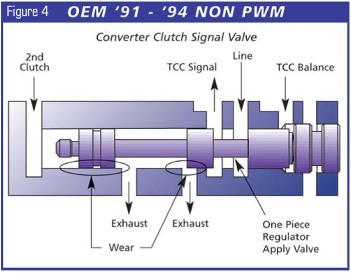
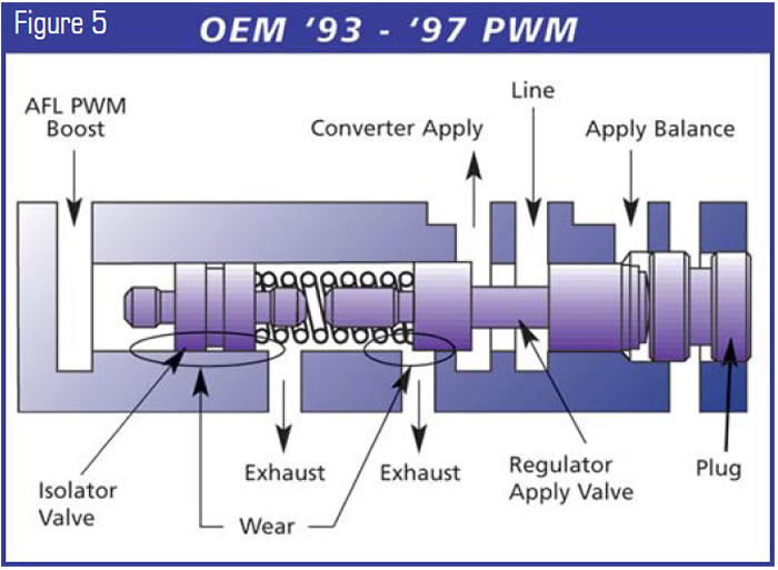
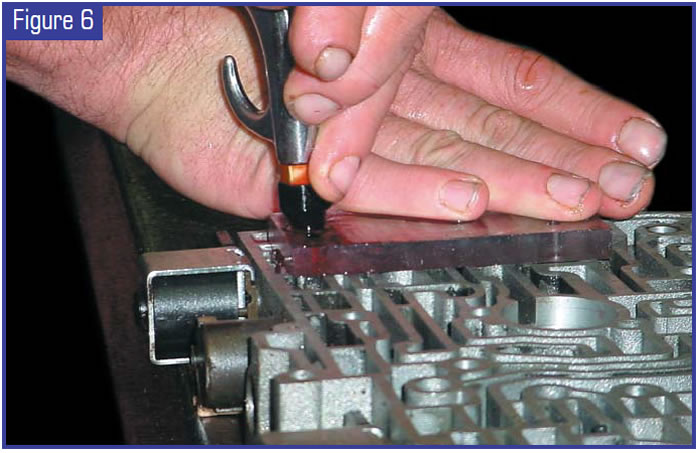
Figure 6 shows a 4L60-E TCC regulator valve being tested. This bore is showing a 1.85-Hz leakage. After removing the valve train, I reamed the valve body and installed a Sonnax TCC regulator-valve kit. Leakage was checked again and the circuit now showed minimal leakage. This valve-body bore is now properly repaired. Pinning this valve will not correct leakage.
This equipment is not a valve-body machine, but it does allow the operator to quickly and accurately test valve bodies for wear before and after any repairs. This will reduce comebacks and increase the quality of your shop’s work.
Another method of testing substitutes a vacuum pump for the hydraulic pump. A good vacuum pump such as an air-conditioning evacuation pump or an air-over-vacuum motor can isolate oil loss past a spool. Using a plate similar to the one mentioned, fitted with a tee to the pump and vacuum gauge, you can “gap”-test the circuit. In theory, this is no different from the hydraulic test described, except for the absence of pressure and mess. The lack of vacuum pulled at the valve-to-bore clearance is similar to vacuum tests on piston rings and valve seats. The great part of this test is the relatively low cost of equipment and identification without disassembly. A negative of vacuum testing is the inability to test Teflon seals, since they require fluid to lift them.
If you have a vacuum source that pulls to 30 inches in one second or less, a rule of thumb for very good or normal tolerance is 26 inches and above. A reading of 22-24 inches means the valve body is marginal and will have signs of polish or scoring. If the test results are 20 inches or less, it must be fixed.

Rick Hoffman is the owner of Custom Transmissions in Bethel, Ohio. The TASC Force (Technical Automotive Specialties Committee) is a group of recognized industry technical specialists, transmission rebuilders and Sonnax Industries Inc. technicians.


