TASC Force Tips
- Author: Maura Stafford
- Subject: Vacuum-testing valve bodies
- Essential Reading: Rebuilder, Diagnostician
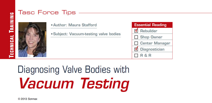
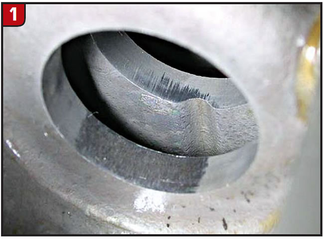
Valve and bore wear occurs when valves repeatedly stroke in a pump or valve-body casting (figures 1 & 2). This wear will eventually increase clearance beyond what is necessary to maintain a proper hydraulic seal, making it impossible for the valve to function properly. Computer adaptive strategy will attempt to compensate for poor performance in some units, but failure ultimately results, codes are set and drivability complaints occur.
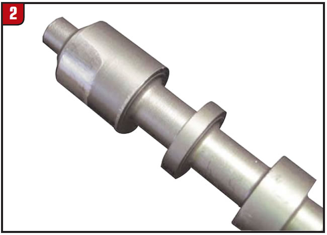
There are many methods to check for and evaluate the severity of worn valves and bores – valve-body testers, visual inspection, wet air testing, measurement tools, wiggle/sag (deflection) tests etc. – but vacuum testing (Figure 3) offers many advantages over other inspection techniques:
- Cost – A vacuum test stand has a relatively low initial cost and requires minimal maintenance.
- Quick and easy – Vacuum testing is easy to learn. Once a routine is established, one or multiple circuits in an assembled casting section can be checked rapidly at the bench.
- Quantitative – Vacuum testing returns a specific value (inches of mercury) that correlates to valve/bore clearance. With experience, you can establish pass/fail standards for determining whether there is too much wear for proper functioning.
- Repeatable – Following a routine calibration and easy test procedures, the system provides repeatable results with negligible operator influence.
- Quality assurance – Wear-induced circuit leaks mean failure. Leaks that are not found lead to customer complaints and comebacks. Vacuum testing can quickly check for unseen wear areas, allowing you to decide whether a valve-body repair is worth the investment and also quickly verify post-repair improvement.
How does it work?
Vacuum testing essentially involves isolating or sealing a circuit containing one or two valve spools and attempting to pull air between the valve spool(s) and the bore. As airflow is restricted by tight clearances, we are able to create, hold and measure vacuum. Since we are rating a vacuum, the measurement will be in inches of mercury or negative pressure.
To maintain a hydraulic seal, there is very little design clearance between the critical valve spool and mating bore. As wear occurs, this clearance increases. A perfect vacuum (no leakage points) will measure 29.9 inches of mercury, although that does change with elevation. Clearance always exists, so no circuit will pull a perfect vacuum. As wear occurs and leakage increases, vacuum-reading levels will decrease. In checking valve clearance, the vacuum loss is directly proportional to the amount of wear.
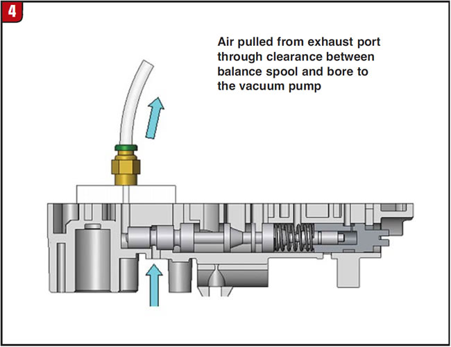
Figure 4 shows a cross-sectional view of a TF-81SC main pressure-regulator valve bore in which the balance-line circuit is being vacuum tested. The vacuum test plate or nozzle seals the balance-line port and tries to pull air from the neighboring exhaust port through the clearance between the valve spool and bore. An extremely good circuit reading might approach 22 or 23 inches of mercury. A severely worn bore could have a reading as low as 8 inches of mercury.

Where should I test?
Vacuum testing should be performed on a clean, dry valve body. You may use either of the following approaches, depending on your situation:
Targeted testing
If you have a specific complaint and there are valves you know are directly related to certain codes or drivability complaints, you may choose to start there. For example, a 4L60-E with an 1870 code should have the TCC-regulator-valve bore vacuum checked for leakage.
General testing
If you do not know where to start, or if you want to evaluate the valve body or pump body more completely, begin by checking different circuits on the basis of their level of valve activity:
- Active valves – The valves doing the most cycling in the bore are most likely to wear first. Boost valves should always be checked because EPC or throttle-pressure changes keep these valves continually moving in their sleeves.
- Modulated valves – Valves reacted on by low-resistance, modulated solenoids tend to wear quickly. These valves oscillate in the bore in a relatively narrow, somewhat-consistent location and are actuated by 32-Hertz solenoids. This is fast enough to modulate the valve, but slow enough to oscillate or stroke the valve in the bore before changing direction. The new-design, faster 300-Hertz solenoids still modulate or position the valve, but much less etching of the bore occurs because they pulse faster than the valve can stroke any significant distance. Examples of low-resistance modulated valves to check would be AODE and 4T60-E converter valves.
- Regulating valves – These valves are controlling pressures to a set parameter, and wear will make the pressure out of spec and possibly set a code. Regulating valves also typically operate in a relatively narrow section of the bore, creating wear at the very location where sealing is the most critical. Examples would be main pressure regulators, secondary regulator valves and solenoid regulator valves.
- On/off valves – Examples include shift valves and manual valves, which don’t move as frequently or don’t oscillate in narrow, linear sections of the bore.
The circuit or port being tested must be captive or sealable.
Balance ports are great locations to perform vacuum tests for this reason. Dense foam or rubber padding can be used to help seal off circuits that are open to the opposite side of the casting. Plexiglas® wet-air-test plates make great tools for sealing off circuits for testing. When sealing a circuit/port for testing, make sure you do not seal off the neighboring port that would supply the air source needed for leak detection, because a false high vacuum reading can result.
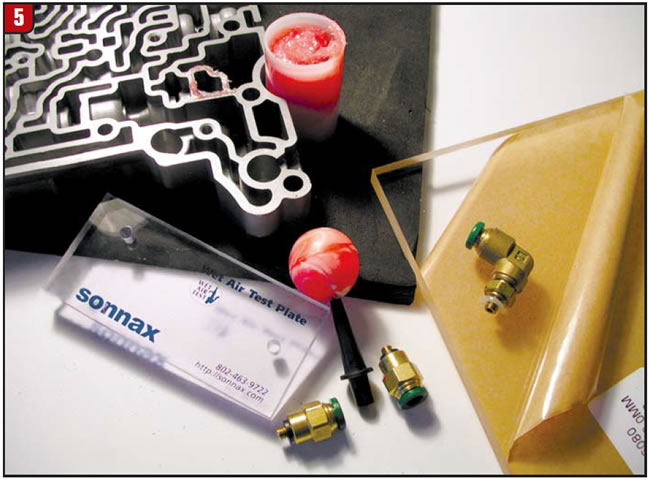
When using a test plate, we recommend that you apply a small amount of assembly lube around the worm tracks of the circuit/port being tested. This provides a much better seal with the test plate, particularly if there are any nicks on the valve-body surface. Checking some locations might require getting creative with test plates. Adapters can be made by drilling through a small rubber ball, disassembling solenoids and using the snout end with O-rings, or by cutting a sheet of Plexiglas to size and using push-connect fittings (Figure 5).
Valves that tend to operate in a narrow, somewhat-consistent location develop wear and are more accurately tested in their operating position. Small checkballs, washers or retainers can be used to position a valve into operating position prior to vacuum testing.
Keeping an oil-circuit diagram handy will help lead you to the key ports for vacuum testing. For units you frequently see in your shop, you should develop vacuum-test data sheets. Show the entire valve body along with the valve locations and ports that should be vacuum tested. Complaints associated with a low vacuum reading at designated ports also can be added as a quick and easy method for evaluating a valve body.
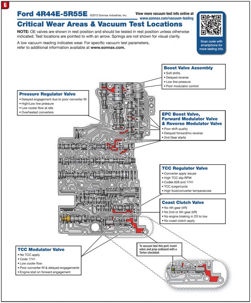
Figures 6 & 7 show specific vacuum-test locations with corresponding targeted complaints commonly found in 4R55E/5R55E units, along with a valve-body exploded-view diagram. More information on vacuum testing as well as additional testing guides can be found at www.sonnax.com/vacuum-testing.
Maura Stafford is a Sonnax project engineer and a member of the TASC Force® (Technical Automotive Specialties Committee), a group of recognized industry technical specialists, transmission rebuilders and Sonnax Industries Inc. technicians.
©2013 Sonnax


