Considering the high cost of transmission repairs, the value of efficient diagnosis has never been higher. Vacuum testing has become a trusted method for identifying valve body problems and verifying repairs. Technicians can easily expand this diagnostic tool to other areas when they understand how it works and the leakage-prone transmission components to target.
The Origins of Valve Body Vacuum Testing
Transmission testing methods evolve and change due to increasingly complex components, especially for testing valve bodies. Many years ago at Sonnax, we recognized there were challenges in accurately diagnosing wear in the newer, lightweight valve body assemblies. Wear of the valve bores and on the valve spools created shift control issues.
These issues were also dependent on whether the oil was thick (cold) or thin (hot). Conventional testing at the time was wiggle testing, wet air testing, flashlight testing, and bore mic testing. These early practices did not give reliable results with the newer, thinner, and more lightweight fluids. Technicians needed more accurate tests to get consistent and repeatable results. It was critical to have the ability to measure wear inside hydraulic control units and retest after repairs to confirm results.
Vacuum testing valve bodies were developed to meet this challenge, as it allows the technician to assign a quantifiable value that corresponded to leaks in the valve bore area. Engine builders already used this method to test for leaking valves, valve seats and guides. Applying vacuum testing to valve bodies provided a cost-effective, repeatable approach and gave precise answers with documented numbers.
How it works: an electric vacuum pump is used to pull a constant vacuum through the space between the casting bore and the outer diameter of the spool. The vacuum value for the valve-to-bore clearance can then be read on a calibrated gauge. This new testing method took the guesswork out of determining wear and was found to be accurate for both lightly worn and high-mileage castings, old and new.
Sonnax understood how valuable this test method could be to shops and took to the road to teach just how simple it was. Through the Sonnax Roadshow, technicians learned how to test and diagnose valve bodies and, when needed, make repairs. They were now able to verify that a repair or replacement was required based on measurable results. (Refer to the Sonnax web page at www.sonnax.com/roadshow to view some videos that will help get started with testing valve bodies.)
Time to Go Beyond Valve Bodies
The same vacuum testing approach used to test valve bodies can also be used on other transmission components and sealed containment areas such as holding brakes and clutch drums. Modern transmissions are much more prone to leaks in these areas than older units. Type F and Dex fluids, the first fluids used in automatic transmissions, would break down and create a varnish build-up.
This varnish sealed leaks in the hydraulic systems and allowed for looser machining tolerances during manufacturing. Unfortunately, the varnish also filled the pores of friction materials with thick pasty fluid that could not be squeezed out when the clutch pack was applied, causing heat and chatter against steel plates or drums.
Modern transmission fluids do not create a large amount of varnish. Therefore, they do not seal leaks like the older fluids did as they broke down. Leaks within the transmission create heat, which causes expansions to increase, which creates bigger leaks. These leaks can be responsible for lifting checkballs in containment areas, exhausting lube oil, preventing it from reaching destinations, and ultimately causing gear, band and clutch failures.
Here are some areas that can cause expensive repeat failures that may be diagnosed with vacuum testing:
- Stator supports in pump covers — this includes both bolted-in and pressed-in supports
- Warpage between pump bodies and pump covers when assembled
- Shafts pressed into clutch drums or housings
- Drum support sealed areas — when used in the middle of the case for clutch feed or fill areas
- Servo bores against servo piston pins
- Bushing leaks — primarily when used to supply clutch fill and supply oil areas
- Check valves and checkballs
- Lube control bushings in case and shafts; and many more.
Let’s look at a few simple vacuum tests that can put a specific value to leakage in an assembly — leaks that a conventional air test won’t find. These vacuum tests, along with proper air testing, help prevent comebacks. An important lesson I have learned is that testing is not to place blame on a component, but to rule out what you know is NOT causing the issue to more easily find what IS causing failures.
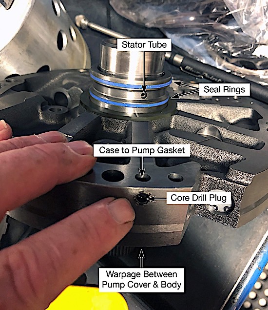
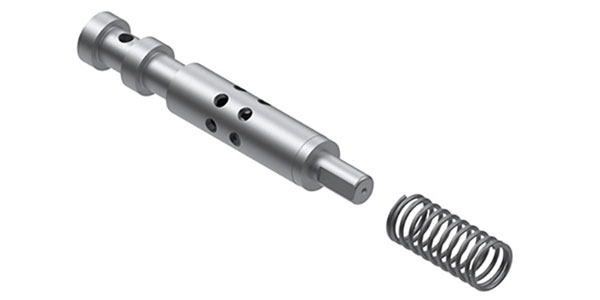
All you need to remember in testing is “oil in = oil out.” During a rebuild on a 4L80-E (based on failed components), the feed circuit that directs the supply of oil to the overrun clutch may be an issue; confirming that it is OK becomes important (Figure 1). The failure with this unit that caused the need for repair was the “overrun clutch was burnt, and the overdrive roller clutch had failed.” These two failures created this no Forward and no Reverse condition.
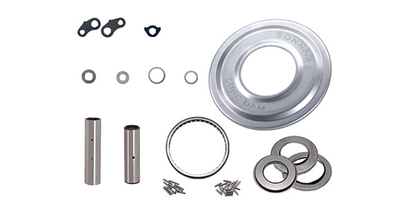
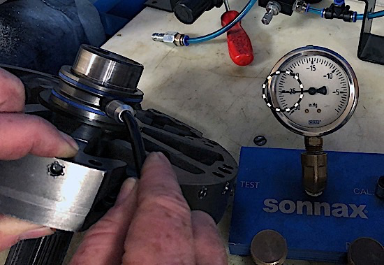
The first test checks for leaks where the core drill plug is used to block the passage from a core drill and where the stator tube presses into the cover. Plug the top and bottom casting drill/oil delivery passage with your fingers and insert a rubber-tipped test tube into the stator tube hole (Figure 2). Gauge results must show zero leakage with 25 in-Hg on vacuum test gauge (if 25” is the seal-off number when calibrated).
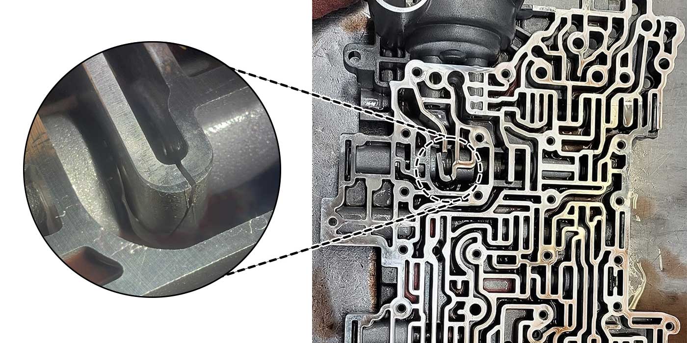
Leakage can also be due to the warpage on the pump as assembled cover to body, so the second test is done with the pump assembled (torqued together). When assembled, install a clamp to ensure outer edges are tight. Plug feed hole with finger and vacuum test on the stator tube hole between the seal rings with a rubber-tipped test tube. Test results should not drop more than 1˝ of vacuum on the gauge. If it drops more than this, the pump should be surfaced to prevent failure.
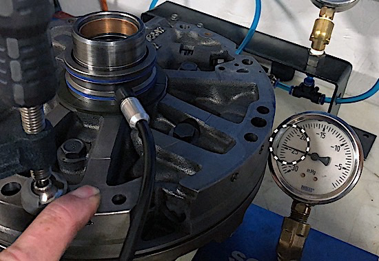
As shown in Figure 3, the original test on just the cover was 25 in-Hg, and now, bolted together, we found only a slight leak with results at 24 in-Hg. This is acceptable because it’s not more than 1˝ of difference. Any greater than 2˝ and you should try to isolate where the leak is. This may include surfacing both sides of the pump and cover.
We will keep illustrating various test procedures in future articles, so keep your eyes open. If you are having issues with any tests and circuits, please let us know by contacting Sonnax Product Support. Until then, keep those transmissions healthy. TD

Randall Schroeder is a Sonnax technical support specialist. He is a member of the Sonnax TASC Force (Technical Automotive Specialties Committee), a group of recognized industry technical specialists, transmission rebuilders and Sonnax technicians.