With the current generation of solenoids and controls, adapting and reprogramming can often be challenging after replacing valve bodies or solenoids, especially in the Ford 6R140. There’s nothing worse than a stubborn vehicle that seems to resist all attempts to get it to shift right after repairs. The strategy Ford relies on for adaptation in its 6-speed models is fairly unique and effective. But for a successful outcome, you’ve got to be familiar with how that strategy works. Not following Ford’s repair guidelines could leave you with drivability concerns after the repair.
Many manufacturers require an elaborate sequence of events for the adaptation to complete successfully after resetting the adapts. This process can fail for a number of reasons, such as the battery charge being incorrect or using the incorrect scan tool. Ford added more complexity to this process when it introduced bands and strategies. To ensure a quick, painless relearn and a successful overall repair that will leave your customer satisfied every time, Ford’s solenoid strategy must be understood and followed.
Ford introduced strategy programming with the 6F50N family of transmissions, followed by the 6F35 and 6R80 families. Older pulse width modulated solenoids needed to pass a very narrow window of performance characteristics, and if they did not, they were scrapped. Ford and others realized they could lower the cost of producing the solenoids by testing each solenoid and assigning each with a banding number between 1 and 5 (Figure 1) based on their flow characteristics.
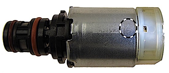
The individual banding numbers and their position in the valve body are then matched to a program in the TCM that would compensate for the performance variation of the solenoids. An algorithm was created to ensure equal pressures were delivered from each solenoid despite their slightly different flow characteristics. Ultimately, this left Ford with fewer scrapped solenoids and therefore lower production costs
The biggest challenge to repairing a 6R140 is complying with the new requirements of the solenoid strategy programming. If replacing a single solenoid, the technician should take note of what the band number is, the position in the valve body, as well as whether it is a normally high or low solenoid so it can be replaced with a solenoid of the same characteristics. Normally high solenoids will have a black plastic snout, while normally low solenoids will have a brown plastic snout. If this information is not recorded before the valve body is disassembled, it can be obtained using a scan tool by inputting the solenoid strategy and ID numbers. The 6R140 solenoid body strategy number will be a 13-digit number; the solenoid body ID number will be eight digits (Figure 2).
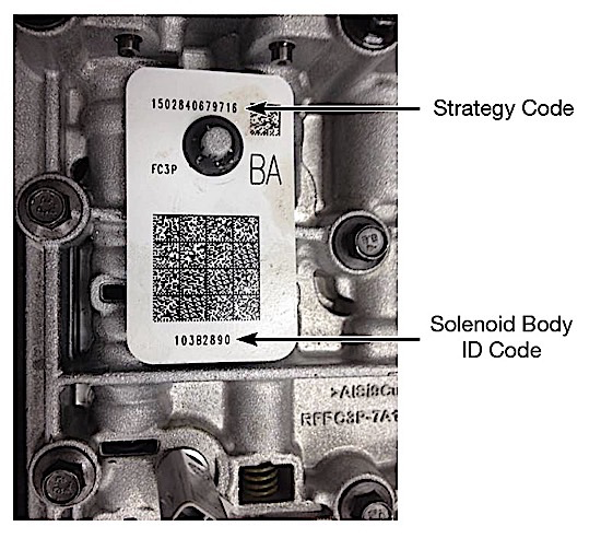
This information can be found on the tag on the valve body. If, after the repair, each solenoid was replaced in the same location with the same band number and type, nothing further should need to be done in terms of programming. However, the keep alive memory should be erased, adaptive values should be cleared, and the following adaptive drive cycle should be performed:
- Start the engine running at operating temperature.
2. Move the shift selector between Neutral and Reverse, Neutral and Drive, pausing between each position for 4 seconds. Repeat the pattern at least two more times or until the shift quality is acceptable.
3. Place the transmission into Drive, accelerate at moderate throttle up to 50 mph, brake lightly to a stop. Repeat the pattern at least two more times or until the shift quality is acceptable.
4. Repeat step 1.
5. Accelerate from a stop to 25 mph, release the throttle, shift the transmission to L range and coast to less than 10 mph. Repeat the pattern at least two more times or until shift quality is acceptable.
Replacing the valve body assembly with a different, new or remanufactured unit requires a different approach. The technician must use the solenoid body strategy number and solenoid body ID from the replacement valve body to update the PCM. Using a Ford scan tool or a J2534 pass-through device, the new solenoid strategy file is uploaded to the TCM. The adaptive tables need to be cleared next, followed by resetting the transmission keep alive memory. Lastly, the Ford-specific drive cycle must be performed.
Failure to follow Ford’s guidelines and blindly replacing solenoids with any band number you have in the shop could result in a flare or harsh shift that could take longer than desired for the TCM to learn the new flow characteristics and adapt to a satisfactory shift. During this lengthy adaptation, the technician runs the risk of damaging the frictions and possibly all the hard work they just put into the unit.
The most challenging part of the repair shouldn’t be the adaptation after the repair. When replacing solenoids, plan ahead and order the correct band numbers that came out of the transmission in the same location as they came out of. When replacing entire valve bodies, make sure that you upload the new solenoid strategy file that comes with it. Following all of these steps will ensure a quicker relearn and a happy customer.
Jason Larochelle is a Sonnax product support representative. He is a member of the Sonnax TASC Force (Technical Automotive Specialties Committee), a group of recognized industry technical specialists, transmission rebuilders and Sonnax technicians.