TASC Force Tips
- Author: Jim Dial
- Subject Matter: 6F35 solenoids, Gen 1. vs. Gen. 2
- Issue: Avoid mismatch; check casting numbers
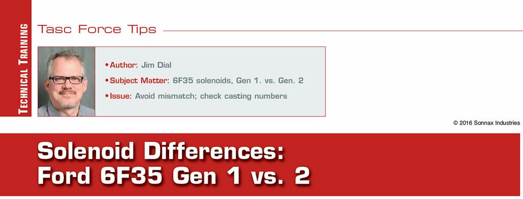
Looking back on the history of the Ford 6T40, the cousin to the 6F35, we recall a second generation of this transmission coming out in 2012. There were many control-valve changes to this valve body as the pressure switches were eliminated and the top cover of the valve body had damper and spring assemblies added to it to provide miniature shock absorbers to each of the solenoid output circuits. This was a new feature to the 6T40. The 6F35, on the other hand, from the start of production, has always utilized one shock absorber, identical to ZF6/6R60/6R80 transmissions (Figure 1).
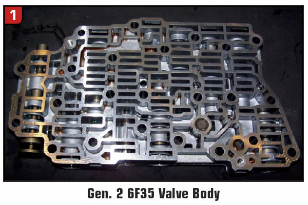
This damper is connected to the 1-2-3-4 solenoid A output circuit as shown in the partial circuit diagram (Figure 2).
This damper helps to absorb the pulses in solenoid output to prevent apply complaints. For example, if this damper were flattened out and could not do its job, there may be complaints such as a harsh or double-bump engagement into drive. Or there may be a complaint of a downshift clunk that could be related to problems with this damper.
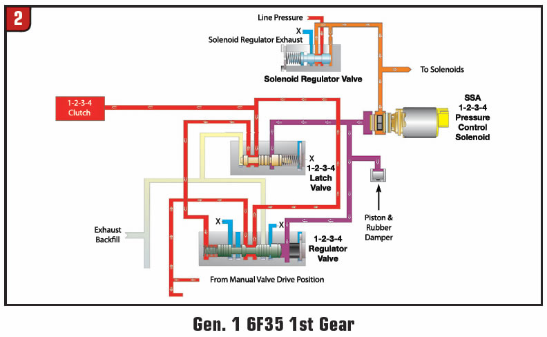
In 2013, the 6F35 came out with a second generation of sorts that incorporated similar changes in the solenoid damper assemblies like its cousin the 6T40, but on a larger scale. Figure 3 shows the location of the 1-2-3-4 solenoid A damper in the main valve body for Generation 2.
Notice that the rubber damper style has been replaced with a piston and spring assembly. Figure 4 shows both the Generation 1 and 2 solenoid bodies together.
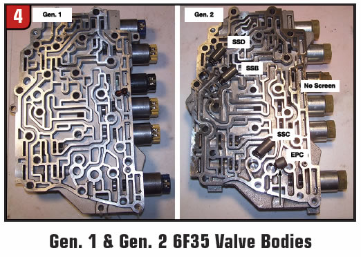

Note that the Generation 1 has no damper assemblies in it. The Generation 2 solenoid body has added four damper assemblies for SSD, SSB, SSC and the EPC solenoid output circuits. Also note in Figure 4 that the ZF6/6R60/6R80 rubber damper shows up in the location for the EPC solenoid. Solenoid design also changed around the time when Generation 2 went into production. Notice the Generation 1 canisters and caps in Figure 4 look similar to the old ZF6/6R60/6R80 design with their blue and yellow caps. Generation 2 solenoids, meanwhile, are similar to the 2010-later 6R60/80 design: band numbers are listed on the canisters and the plastic caps are almost a clear color. Note: These solenoids are not interchangeable with the 6R60/80.
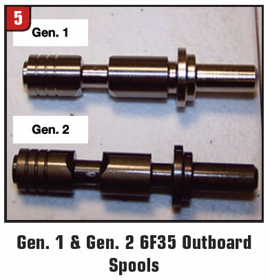
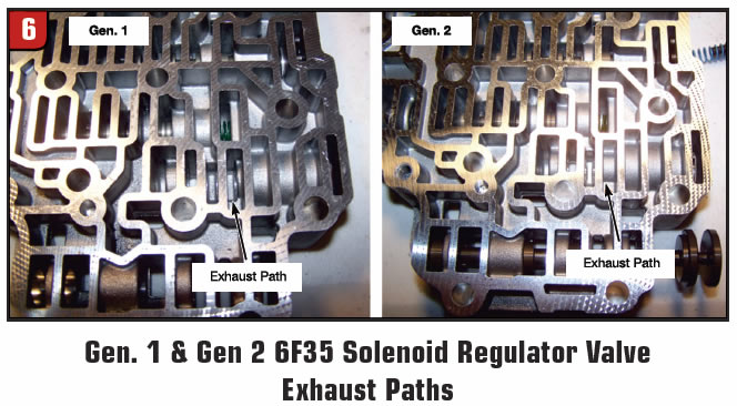
The control valves in the valve body for Generation 2 did not change like the 6T40, as the 6F35 did not incorporate pressure switches into its circuitry. However, the solenoid regulator valve and the valve body casting were changed for Generation 2. Figure 5 shows the outboard spool on the Generation 2 solenoid regulator valve longer in length, and Figure 6 shows the exhaust path for the solenoid regulator valve is now closed.
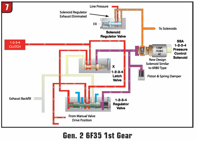
These changes and the new design damper and spring can be viewed in a partial hydraulic circuit diagram (Figure 7).
It is obvious, but must be said, that Generation 1 and 2 are not interchangeable, so identification is key. There will be a substantial difference in solenoid apply strategy/programming between not having dampers and having them. This change to Generation 2 came out sometime in 2013 and can be easily identified with casting numbers. Generation 1 can be identified with the casting numbers of 9L8P or BL8P-7A100 (Figure 8).
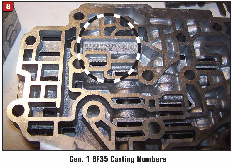
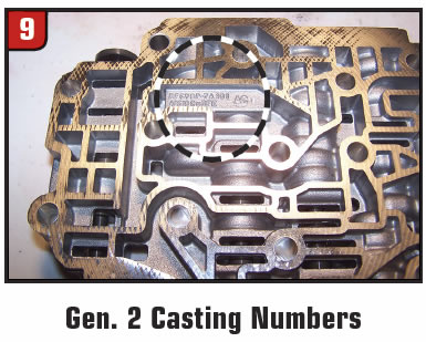
These casting numbers are on the main valve body, the solenoid body and the molded lead frame that the solenoids attach to. Generation 2 casting numbers are CV6Z-7A100 and can also be found on both valve body sections and the molded lead frame for the electronics (Figure 9).
In closing, be sure to verify what generation 6F35 you are working on by using the casting numbers. This will prevent any parts mismatch, customer complaints and warranty repairs.