Souza Sezz
- Author: Mike Souza, Contributing Editor
- Subject Matter: 10R80/10L90
- Issues: Solenoids: electronic & hydraulic function
10R80/10L90 10-Speed Solenoid Function
In the last article we identified the solenoid locations and shift application. This month I would like to discuss the electronic and hydraulic function of the solenoids and also cover solenoid replacement.
Here are overviews of the 10R80 and 10L90 transmissions (Figure 1).

The first thing to remember when replacing the valve body and/or just the solenoids is the TCM will have to be updated. This is very similar to what has been covered in the past with the 8L90 found in GM vehicles referred to as solenoid characterization. The 10R80 solenoids are similar to the 6R140W solenoids referred to as solenoid body/strategy identification.
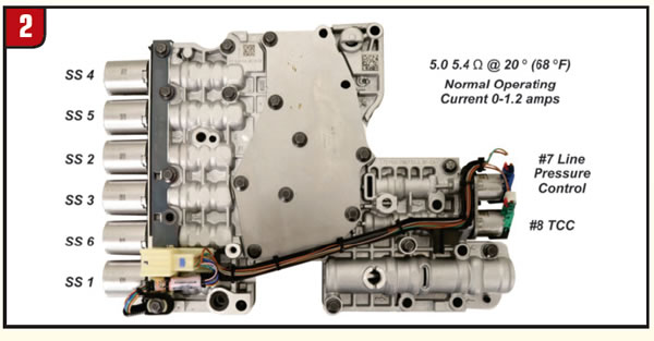
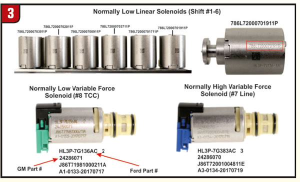
The GM transmission control solenoid valves 1 through 8 (Figure 2) are pressure-regulating valves. Each solenoid valve is tested after assembly to determine the output fluid pressure (flow rate) at certain electrical values, applied to the coil winding. This information is referred to as solenoid current/ pressure data points. The solenoid valves are tested two ways, with an increasing and then a decreasing electrical current applied to the coil winding. The current versus pressure data-points results are saved and assigned a file number. This file number is marked on the solenoid valve housing end or on the valve body itself (Figure 3). The solenoid performance data file is stored on the Techline Information System (TIS) website. This data file is programmed and stored in the vehicle’s TCM. Replacing any of the following components will require the TCM to be programmed with either the new or existing solenoid valve performance data, depending on what component is replaced.
- Transmission assembly
- Lower control valve-body assembly with solenoid valves
- Transmission control module
- One or more solenoids
On the Ford 10R80 transmission models, the solenoid body/strategy identification is as follows: The 13-digit solenoid-body strategy number consists of only numbers (1). Letters are not used. Compare the solenoid-body identification and strategy to the solenoid-body identification tag located on the left side of the transmission case. If the solenoid-body identification and strategy displayed on the scan tool match the solenoid-body identification tag or replacement tag, then the solenoid-body identification and strategy are correct for this transmission and a solenoid-body strategy data download is not required. If the solenoid-body identification tag or replacement tag is missing or damaged so it is not readable or does not match the identification or strategy displayed on the scan tool, remove the transmission fluid pan and filter and locate the 13-digit solenoid-body strategy etched on the main control casting (Figure 4).
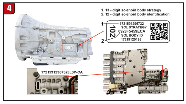
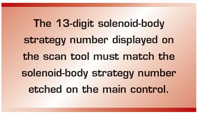
The 13-digit solenoid-body strategy number displayed on the scan tool must match the solenoid-body strategy number etched on the main control. If the numbers do not match, damage to the transmission or driveability concerns can occur. If the new main control was not supplied with a replacement solenoid-strategy identification tag, DO NOT INSTALL the main control as all required programming information is missing. Compare the solenoid-body strategy identification etched on the main control to the solenoid-strategy identification tag on the transmission case. If the solenoid-body strategy identification etched on the main control does not match the solenoid-strategy identification tag, then a solenoid-body strategy data download is required. If the solenoid-body strategy etched on the main control does match the solenoid-strategy identification tag on the transmission case but does not match the 12 digit solenoid-body identification and strategy displayed on the scan tool, then a solenoid-body strategy data download is also required.

Let’s take a quick look at the hydraulic functions. Solenoids 1-6 are normally low linear solenoids for shifts and regulated line-pressure clutch control (Figure 5). When these solenoids are off; they provide pressure to stroke the clutch control valve allowing controlled line pressure into the apply clutch circuit. When turned on, no pressure to the control valve (stationary) line pressure will be blocked from entering the clutch apply circuit. The solenoid accumulator keeps the solenoid-signal pressure smooth. Both the power and ground circuits are controlled by the TCM. Note: Although these solenoids work the same way, each has a different part number for different flow rates and should be installed at their original locations.

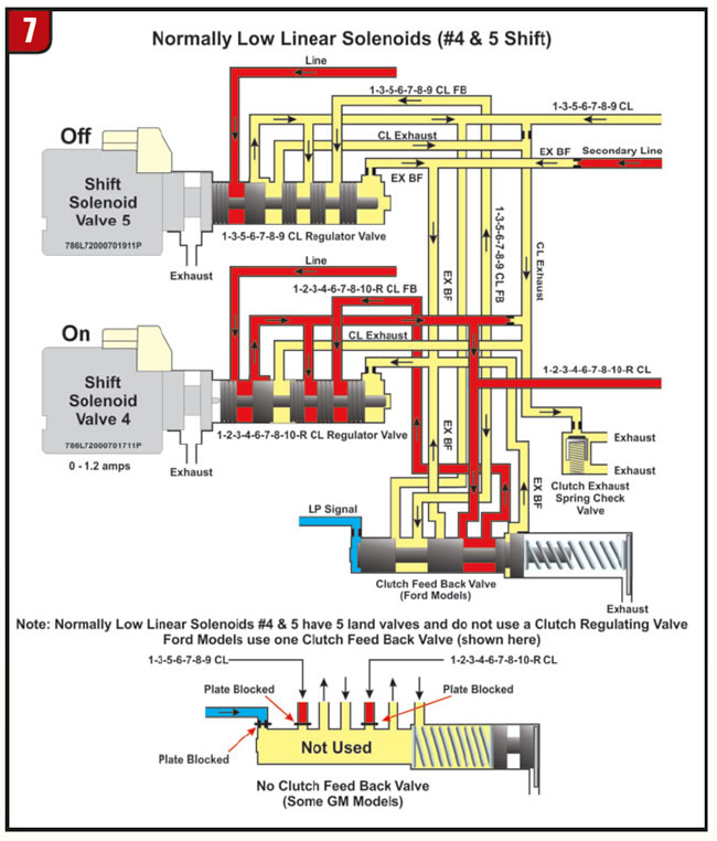
Shift solenoid valves 1, 2, 3 and 6 have a 4 land regulating valve (shown in figure 5) whereas, shift solenoid valves 4 and 5 have a 5 land regulating valve shown in Figure 6. Note: On shift solenoid regulating valves 1 and 2 there is an inner valve land that is opposite of each other (figure 5).
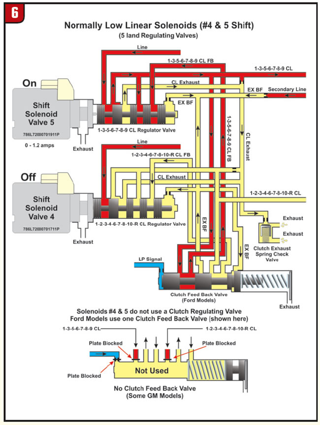
Figure 7 shows the change in hydraulic function when solenoids are turned on and off. Note: In figures 6 and 7 there may be a No Clutch Feed Back Valve found on some GM models. Although the GM factory hydraulic diagrams show the valve missing on the valve body we have at the Seal Aftermarket Tech Center, the valve was present but the separator plate feed orifices where missing preventing oil flow to the valve.
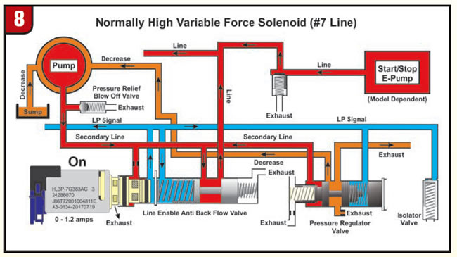
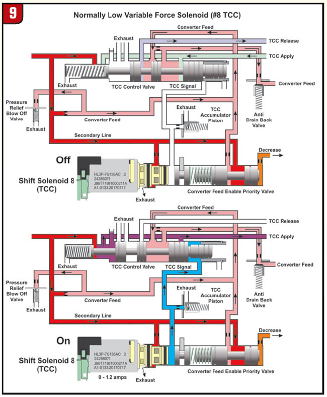
The line pressure solenoid (#7) is a normally high variable force solenoid with the hydraulic function show in Figure 8 and the TCC solenoid (#8) is a normally low variable force solenoid with the hydraulic function show in Figure 9. More information about the unusual speed sensors and other electronics on this new 10-speed from Ford and GM will be covered in our next article. We will also cover the new unique sump filter function and strategy. Thanks for reading see you soon!