Torque Converter Tech Tips
- Subject: Orifice control within the converter
- Essential Reading: Rebuilder
- Author: Ed Lee
Parts 1 and 2 of this series briefly touched on the secondary oil paths through TCC pistons, turbines and stator caps. This final article will cover regulation and possible restrictions of converter-charge/TCC-release oil flow.
The secondary path of the charge/TCC-release oil is regulated to some degree by transmission parts within the confines of the converter. In some units, the charge oil is regulated by the orifice created between the raised area on the stator shaft (or support) and the impeller hub. In other units, it is regulated by restricting the flow of oil through or around the input-shaft bushing mounted inside the stator support. The Allison 500 series is a unique example because it uses both methods to regulate oil flow, as it both enters and exits the converter.
Some transmissions have a separate torque-converter regulator valve that works in conjunction with the main pressure-regulator valve. The BorgWarner transmissions (T-35 Model 12 and FMX) are early examples of this design where the valve was used to control the flow and regulate the pressure at about 40 psi.
Inside the converter, the path of the charge/TCC-release oil needs to be as free of restrictions as possible. In lockup converters, except those using a clutch-pack type lockup system, the most-popular path for charge oil is through the input shaft, then crossing in front of the TCC. Possibilities for flow restrictions will vary depending on the stack-up of the converter. For lockup converters that stack up without the turbine hub contacting the cover, the only possible restriction is insufficient clutch-release clearance. (For more information, see the 4R100 article in May 2006 Transmission Digest, page 20.)
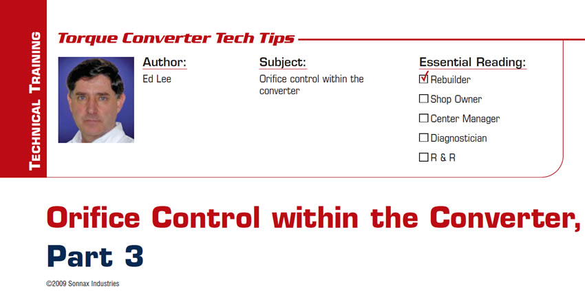
Converters that stack up with the turbine hub contacting the cover have several possible areas where restriction can occur. The thrust washers or bearings that separate turbine hubs and covers are one possible area. For example, the bearings in FWD Chrysler converters are designed to pass oil (Figure 1), while bearings in RWD Chryslers are not designed to flow oil and may cause a restriction (Figure 2).
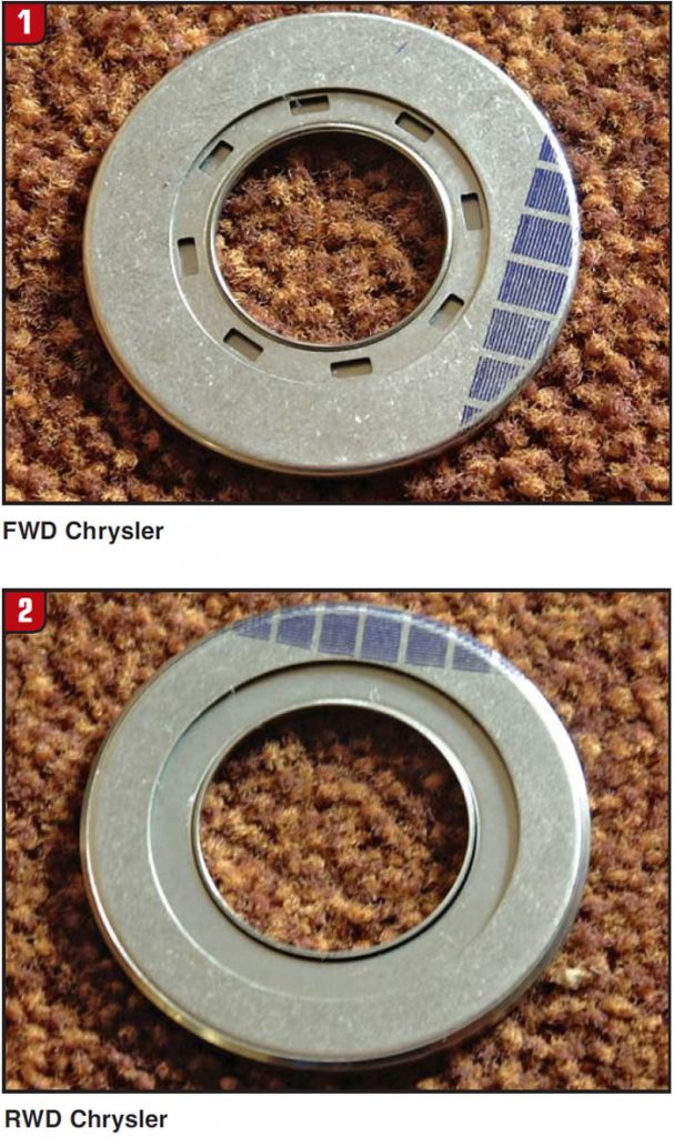
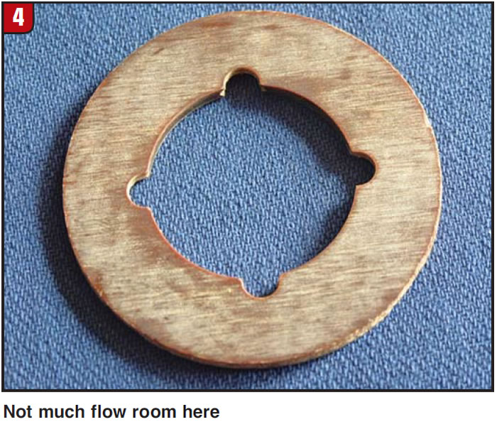
Thrust washers have similar flow issues. Always check to make sure that flow passages are present and that they are not blocked by improper installation (figures 3 and 4).
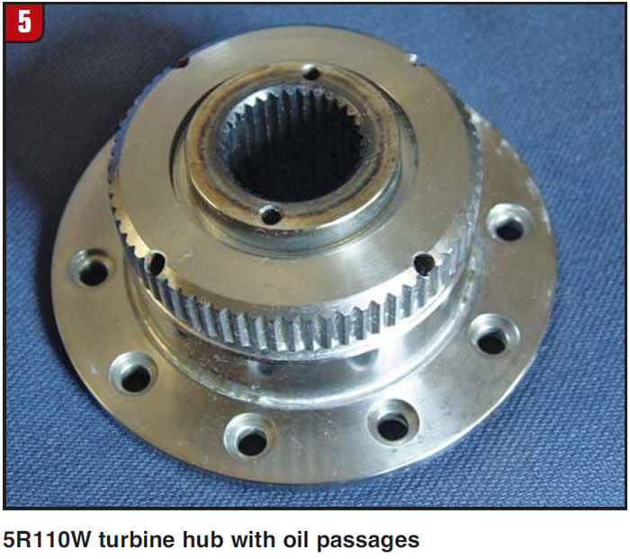
If the bearing or thrust washer restricts the flow of TCC-release oil crossing between the piston and cover, make certain that a secondary path is available. Grooves in the cover (e.g., Cummins) or passages through the turbine hub (e.g., 5R110W) will both work (Figure 5). (For more information, see the 740-1740 article in September 2005 Transmission Digest, page 52.)
Testing conducted with ATF at 180° F at 80 psi has shown that the flow rate of the release oil passing between the lockup clutch and the cover should be at least 4.5 gallons per minute.
With regard to oil flow within the converter, one question always comes up: How can oil-flow rates within the converter exceed the volume capacity of the transmission pump? In reality, the transmission pump has a very limited role when it comes to oil flow within the converter. The transmission pump’s only role is to supply converter-charge oil. That can be further divided into two categories: charge/TCC-release oil in non-lockup mode and TCC-apply oil in lockup mode. The flow of oil for all the secondary oil paths is supplied by the converter’s internal pump: the impeller.
The transmission pumps with the lowest flow rates, such as in some Hondas and Toyotas, will pump a maximum of about 1.8 gpm. Transmissions with the small pumps will usually have 5/16-inch-diameter cooler lines. Transmissions with medium-sized pumps will usually have 3/8-inch-diameter cooler lines and flow rates as high as 2.6 gpm. 47RE and 48RE transmissions are good examples of these. Transmissions with the largest pumps can be identified by their 1/2-inch-diameter cooler lines; some are capable of pumping more than 6 gpm, such as the Allison 1000/2000/2400.
The impeller is a much larger pump than the transmission’s pump. In domestic vehicles the smallest impeller is an 8-inch found in Opels. Other domestic-vehicle impellers can be as large as 13-inch, and those in many commercial vehicles are much larger. It is easy to understand the larger secondary flow within the converter when you realize that the converter impeller is capable of pumping many times more oil than the transmission pump.

Ed Lee is a Sonnax Technical Specialist who writes on issues of interest to torque converter rebuilders. Sonnax supports the Torque Converter Rebuilders Association. Learn more about the group at www.tcraonline.com.