Leeward Tech
- Author: Ed Lee, Contributing Editor
- Subject Matter: Torque converters
- Issue: Three possible paths for oil
Inside the converter
Plotting the pathways of the oil that enters and exits the converter is not an easy task if you are only looking at the parts of the converter. Adding a stator support and an input shaft to the converter parts makes this task somewhat easier.
There are three (3) possible paths for oil to take to get in or out of the torque converter. The most obvious path is between the inside diameter (I.D.) of the impeller hub and the outside diameter (O.D.) of the stator support. The other two (2) passageways live within the I.D. of the stator support. If the transmission has a solid input/turbine shaft the oil must pass between the O.D. of the input shaft and the I.D. of the stator support. If the transmission has a hollow input/turbine/ shaft, the oil can travel through the input shaft.
All three (3) of the passages are unique and have changed through the years. All of the early converters were filled through the passage between the I.D. of the impeller hub and the O.D. of the stator support. This method was used until the introduction of the lockup torque converter in the late 1970s. To turn the lockup on or off an extra valve or two (2) was added to the transmission. The added valves were “switch valves,” “lockup control valves” or with the three (3) path converters “bypass valves.” The valves were used to reverse the in and out flow of the converter to apply and release lockup. The torque converter clutch (TCC) piston in the lock up torque converter worked like a one-way valve.
In the TCC release mode, charge oil and TCC release oil are one and the same. The charge/release oil would travel either through or around the input shaft and exit in front of the TCC clutch. From here it would travel between the cover and TCC clutch, floating it off of the cover and continue past the O.D. of the TCC clutch. It would then exit the converter through the passage that was previously used to charge the converter.
When the lockup mode is commanded, the in and out flow of the converter is reversed. At this time, the TCC apply oil is divided. One part of the TCC apply oil enters the converter through the early converters charge oil passage. When this oil gets to the TCC piston it moves it forward against the cover, closing off the exit passage. The other part of the TCC apply oil is directed to the cooler and returns to the transmission as lube oil. The oil in front of the TCC clutch is metered out of the converter to exhaust to regulate TCC apply feel.
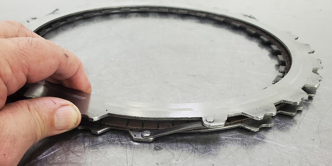
Since there is no cross passage in the stator support, oil must travel to the front of the stator support to reverse direction. The inner race for the stator is splined to the front of the stator support and it will not pass oil. The turbine side stator cap is the first place that the oil can cross to the reverse direction. In the TCC release mode there are three (3) possible pathways for the oil to reverse direction: 1st pathway, between the TCC piston and cover; 2nd pathway, between the TCC piston and turbine; and 3rd pathway, between the turbine and stator. In the lockup mode the turbine side stator cap is the only path in or out of the converter. For this reason this cap should never be restricted. All of the original equipment (OE) turbine side stator caps will flow between 30 to 32 gallons per minute (GPM).
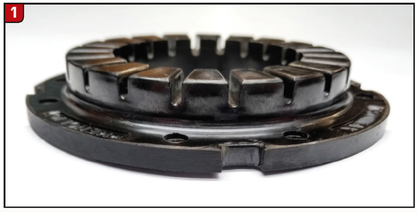
The flow through this stator cap (Figure 1) has a direct connection to the efficiency and the regulation of temperature in the converter. If this flow rate is less than 10 GPM the converter will overheat before it gets off of the lift. Be alert to any possible flow rate restrictions on after-market stator caps, especially bearing adapters.

Regulating the flow
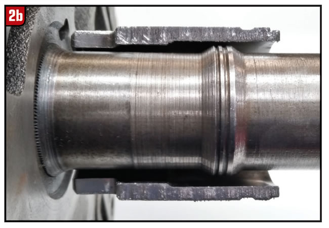
The flow of charge oil into the converter is regulated on all transmissions. Most of the regulation is done by the pressure regulator valve, but sometimes an orifice is also used. In many cases the oil exiting the converter is also regulated. This task is usually done by metering the oil through the gaps in the front stator support bushing. The 540/545 Allisons and most of the early rear wheel drive Fords are the best examples of this. There are also some regulating factors that many rebuilders do not think about. With the exceptions of the Dynaflow and Powerglide, all of the early General Motors and Chrysler transmissions that used torque converters had a raised area on their stator supports.
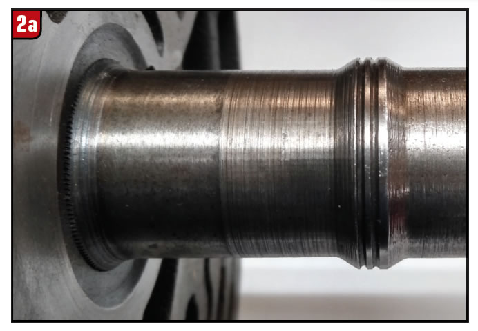
This raised area (Figure 2A) looks like a rough machined surface, but the O.D. is incredibly accurate. The orifice created by this raised area and the I.D. of the impeller hub (Figure 2B) not only regulates charge oil volume, but also is an influence on the balance oil at the P.R. valve. Many rebuilders learned this the hard way when they installed 350/400 impeller hubs on torque flight (TF) 8 converters. The 350/400 and the TF 8 impeller hubs have the same O.D. dimension, but the I.D. on the 350/400 hubs is smaller than the TF 8 hub. Not only did it take forever to fill the transmission with oil but it also killed performance. Who would have guessed that you could increase the performance of a converter by boring the I.D. of the impeller hub to the proper specifications? This is one area where that the early torque converter parts suppliers dropped the ball.
Many of the early parts suppliers used steel tubing to make their impeller hubs. They would machine the O.D. to the proper specification, but leave the I.D. untouched as long as it did not contact the stator support. Even when the manufactures started machining the I.D. on the impeller hub, some had an I.D. run out specification as liberal as +/- 0.015”. This was not acceptable. This is just one of many good reasons for not using the I.D. of the impeller hub for fixture purposes.
Purpose oriented orifices
When TCC apply is commanded, the TCC piston is force forward to contact the cover. For this to happen, the oil between the TCC clutch and cover must exit this cavity. The faster the oil can exit this cavity, the faster the TCC piston moves forward and the firmer the lockup feel. One early lockup system used a cut out in the spacer plate next to the switch valve to regulate this oil (Figure 3).
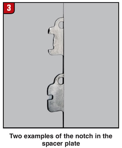
This method worked, but could have worked better if the oil did not have to travel 10 to 11 inches to get to the orifice. The saving grace was that the orifice was downstream from the switch valve and only had to regulate the oil in one direction.
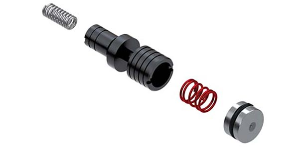
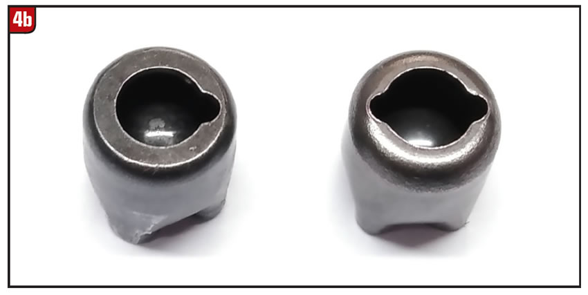
Another lockup system used a check ball capsule locate between the TCC piston and the controlling valve. The check ball capsule could control the flow of oil in both directions. For converter charge the check ball would unseat for full flow. To meter the flow for lock up feel, the check ball would seat and only allow the oil to pass through the notch at the edge of the check ball seat. This notch came in different sizes for different torque requirements.
The four (4) cylinders and small V6 power plants used the smallest notch and the size of the notch increased as the torque requirements grew. You cannot see the size of the notch when the check ball capsule is in the input shaft. Many complaints of too firm or too soft of a TCC apply were caused by replacing the input housing. For most performance applications the check ball capsule is left out.
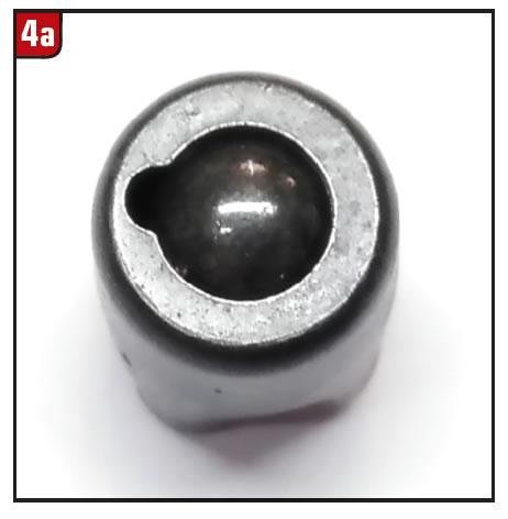
The single capsule shows the ball seated (Figure 4A), and the two capsuled show the different notched (Figure 4B).
Today, most of the orifices that regulate lock-up feel are located in the valve body spacer plate. Hope this helps to better understand the “ins and outs” of torque converters.