
Torque Converter Tech Tips
- Author: Ed Lee
One of the more-frequently asked torque-converter questions is about the 0.028-inch orifice found in some General Motors 298mm and 300mm TCC pistons with carbon-weave lining (Figure 1).
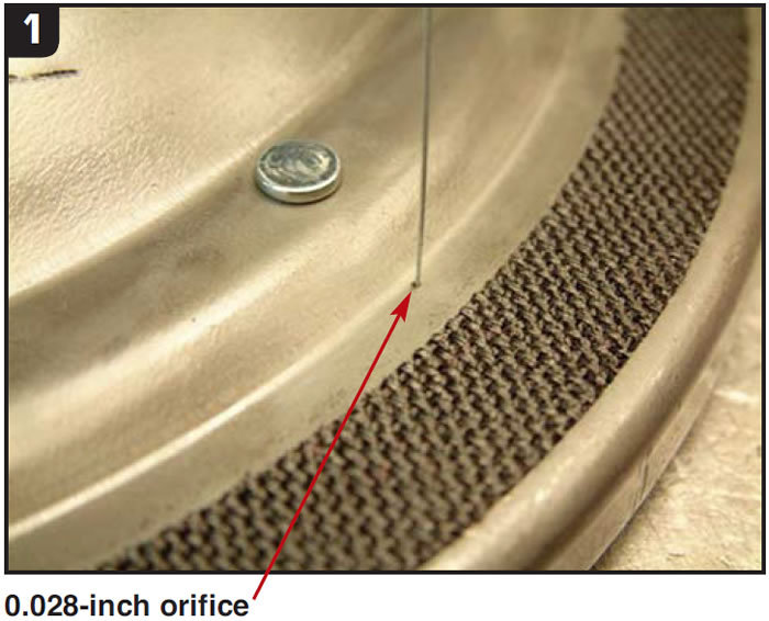
Converter rebuilders want to know why some of the pistons have the orifice and some do not. The answer to this question begins with understanding why the orifice was used in the first place. The orifice was drilled through the piston to help cool the mass of the converter. The TCC-release passage is open to exhaust when the converter is in the TCC-apply mode. Metered oil, which is allowed to bypass the piston by way of the orifice, carries some heat away from the converter.
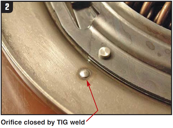
The original-equipment manufacturer (OEM) later discovered that the loss of clamping force caused by the leakage through the orifice was not worth the extra cooling gain. For this reason the orifice is being phased out of production and will not be in new models. The TCC pistons in some foreign converters also had a similar orifice, but only in a limited number of applications. Today, the best approach for a rebuilder is to close the orifice with a small TIG weld (Figure 2).
Another popular torque-converter question is about the three 0.185-inch-diameter holes in the 300mm turbines (Figure 3).
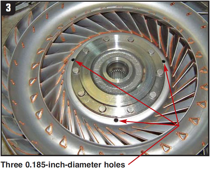
Rebuilders often ask why they are found in the 300mm turbines and not in the 298mm turbines. To answer that question, you need to know how the lockup function differs between the two converters. In the 298mm converters, the turbine hub comes into contact with the conical washer that is in contact with the cover. In this type of converter, the TCC piston is free to move forward and backward for lockup apply and release, independently of the turbine hub. In the 300mm converter, the turbine hub is not held in a fixed position relative to the cover. In this type of converter, the turbine and TCC piston move forward and backward as a unit for TCC apply and release.
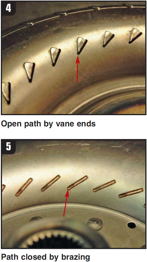
In either design, the volume of oil that escapes past the outside diameter of the turbine (between the turbine and impeller) is not enough to provide adequate TCC-apply pressure and reduce the forward forces on the turbine. An additional oil supply is needed to provide the required feed and balance oil. In 298mm converters, the small gaps at the end of the vanes provide a secondary path for balance oil (Figure 4). That path is not open in 300mm converters because their turbines are furnace brazed, which closes the holes (Figure 5). The three 0.185-inch holes provide the secondary oil path.
Keep this in mind the next time you are using a furnace-brazed turbine to build a performance converter. You may want to add a few holes to balance forward thrust.
The amount of oil needed to balance the thrust loads on the turbine seems to be fairly consistent. The three 0.185-inch holes in the 300mm turbine will pass about 26.8 gpm at 80 psi at 180°F. The four 0.165-inch holes in the Allison 1000 converters will pass 28.4 gpm under the same conditions. A similar amount of oil was able to pass through the gaps at the end of the vanes on the 298mm turbines.
Next month we will cover the holes that allow oil to pass through the stators and turbine hubs.


