Hydraulics Fundamentals: Shift & Relay Valves - Transmission Digest

Hydraulics Fundamentals: Shift & Relay Valves

Shift valves and relay valves share a lot of the same duties. This article is one of a series by Sonnax exploring how valves and hydraulic circuits work and what results when they quit functioning correctly.

An understanding of hydraulics is essential for properly diagnosing and repairing transmission problems. This article is one of a series by Sonnax exploring how valves and hydraulic circuits work and what results when they quit functioning correctly.

Shift valves have been around the automatic transmission world from day one. These types of valves are pretty much the gatekeepers that connect line or clutch pressure to clutch apply and/or clutch exhaust circuits. In the past, these valves were controlled by governor circuits that would open and close the shift valve based on how fast the vehicle was moving down the road. In today’s transmissions, shift valves are typically controlled by ON/OFF shift solenoids and/or clutch pressures that are controlled by clutch pressure control solenoids. 

Figure 1 shows an example of a typical shift valve function in today’s transmissions. The diagram shows the 6L80 engagement process into Drive first gear from the Park position. Shift solenoid 1 – which is an ON/OFF solenoid – is turned ON, which strokes clutch select valve 2 to the left. This connects CBR1 pressure from pressure control solenoid 3 through clutch select valve 2 – which is functioning as a shift valve – to the low Reverse apply circuit. This connection provides a backup for the low sprag by the low Reverse clutch during launch in first gear.

figure 1

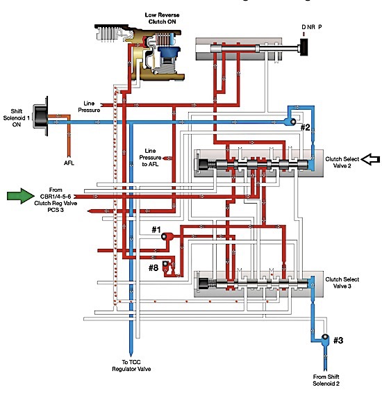
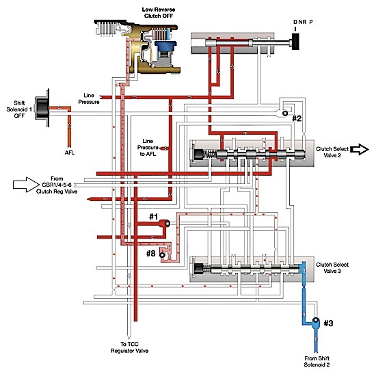
Figure 2 shows shift solenoid 1 turning OFF – this happens when vehicle speed is increased to a little less than 10 mph. When shift solenoid 1 is turned OFF, notice that clutch select valve 2 is moved back to the right by spring pressure. This provides an exhaust path to the low Reverse clutch and pressure from clutch pressure control solenoid 3 is decreased. So, in conclusion, shift valves of today are still the same – and have the same type of function – as earlier designs. In this instance, you can see that vehicle speed is a factor for low Reverse application in first gear. The difference is that modern transmissions get vehicle speed information through electronic speed sensors, not through hydraulic governor pressure.

figure 2

Relay valves have a very similar function to shift valves. The word “relay” means to receive and pass on, kind of like the old relay race baton hand-off back in high school. 

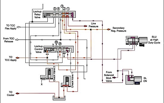
Figure 3 shows a representation of the U760 transmission lockup relay valve in TCC OFF mode. When in this mode, the lockup relay valve receives line pressure to connection point number 1, which is blocked. Secondary regulator pressure is fed to connection point 3.

The relay valve passes it along to the TCC release circuit to keep the torque converter clutch from applying and on to connection point A in the lockup control valve. This passes on this pressure back up to connection point 4 of the lockup relay valve, where it is blocked. Connection point 5 receives pressure from the TCC flex apply circuit, which is blocked by the valve. The TCC release circuit connects to the TCC apply circuit through the torque converter and is fed to connection point number 2, where it is sent off to the cooler. 

figure 3

Figure 4 shows these valves when TCC is fully ON. The SL solenoid is turned ON by the powertrain control module, and the lockup relay valve strokes to the left. This action connects secondary regulator pressure from connection point 3 to the TCC apply circuit at connection point 2, which feeds apply pressure to the torque converter clutch.

At the same time, TCC release pressure is connected to an exhaust path at connection point 4 at the lockup relay valve and is exhausted at connection point B at the lockup control valve, when the SLU solenoid strokes it to the left at high duty cycle. Connection point 1 at the lockup relay valve then connects the cooler circuit to line pressure to help cool the transmission.

figure 4

In conclusion, shift valves and relay valves share a lot of the same duties. Hopefully this information will help when diagnosing a shift or relay valve-related problem so you don’t drop
the baton.

Jim Dial is a Sonnax technical specialist and a member of the Sonnax TASC Force (Technical Automotive Specialties Committee), a group of recognized industry technical specialists, transmission rebuilders and Sonnax Transmission Company technicians.

You May Also Like

Sherlock Holmes Approach to an AB60 No-Move Situation

The effectiveness in diagnosing automatic transmission malfunctions is an art form. Although there are similarities among the wide varieties of transmissions on the road, each transmission has its own peculiarities. Aside from having mechanical, hydraulic, and electrical hardware systems to contend with, software/programming issues and various vehicle platforms make diagnostics much more difficult.  Using scopes provides

ab60

The effectiveness in diagnosing automatic transmission malfunctions is an art form. Although there are similarities among the wide varieties of transmissions on the road, each transmission has its own peculiarities. Aside from having mechanical, hydraulic, and electrical hardware systems to contend with, software/programming issues and various vehicle platforms make diagnostics much more difficult. 

GM 6T40 Pump Identification Guide

The 6T40 was introduced in 2008 for General Motors front-wheel-drive cars in the Chevrolet Malibu and has gone through several changes throughout its three generations, specifically in the pump area. The 6T40 is closely related to the more lightweight 6T30 and the heavier duty 6T45 and 6T50. Generation one started phasing out during the 2012

Seeing the Forest AND the Trees

They say that the proverbial phrase “I couldn’t see the forest for the trees” means that a person or organization cannot see the big picture because it focuses too much on the details. Related Articles – 4L60E Harsh 1-2 Shift – TASC Force Tips: Diagnosing 8L45 & 8L90 Shift Complaints – TASC Force Tips: Hydraulics

The Manifold Pipeway

The Honda six-speed transmission has been on the bench of many specialty shops for one reason or another (figure 1). But, for those of you who have yet to lay your hands on one, mounted on the upper side of the unit is one of the largest, if not the largest solenoid and pressure switch

8L90 Vacuum Testing

Below are the diagrams for vacuum testing GM 8L90 transmissions. Note: OE valves are shown in rest position and should be tested in rest position unless otherwise indicated. Test locations are pointed to with an arrow. Springs are not shown for visual clarity. A low vacuum reading indicates wear. For specific vacuum test information, refer

Other Posts

Shift of the shaft: Diagnosing Chrysler 48RE manual shaft issues

The TorqueFlite transmission has been around since mid-to-late 1950s. There have been many changes surrounding the manual shaft and rooster comb through the years. This transmission shaft controls the position of the manual valve that directs oil for the gear ranges, but it also is used for a Reverse light control as well as Park/Neutral

Diagnosing Ford 10R60, 10R80 and 10R140 series speed sensor issues

Ford 10-speed 10R series transmissions utilize four two-wire, Hall-effect sensors — TSS, ISSA, ISSB and OSS — for providing speed signals to PCM or TCM. They are supplied nine volts by a PCM or TCM and assist in the control of clutch apply/release timing that is used in determining shift quality, including TCC. Related Articles

Easy TH400, 4L80-E reverse servo setup: Craft your own tool

While not as sensitive as some shifting bands, the Reverse band adjustment on a TH400 or 4L80-E transmission is critical, and failure to get it right has tripped up even the best builders. There is nothing worse than getting the transmission installed, putting it in Reverse and then not going anywhere or having no engine

Understanding lube flow control valves in Toyota/Lexus UA/UB80 transmissions

The Toyota/Lexus UA80 and UB80 transmissions first came out in 2017 in Highlanders and Siennas. The UA80 is used in V6 applications, and the UB80 is paired with four-cylinder versions. They have been called Toyota New Global Architecture type transmissions, and alternately referred to as the “Direct Shift 8AT” eight-speed automatic transmission. This transmission was

Tasc-Tip-December-Figure-1---LFC-Valve-OE-Partial-Circuit-Diagram-1400