
Torque Converter Tech Tips
- Author: Ed Lee
Converter charge oil performs a number of important functions: It fills the converter in a timely manner. It keeps the lockup clutch off the cover in the release mode. It also eventually becomes the lube oil for the transmission.
When charge oil is not flowing at the correct rate, the converter will operate less efficiently, the lube oil to the transmission will not be adequate and the lockup clutch will drag on the cover in the TCC release mode. The TCC apply can feel more pronounced and could shudder because of a greater differential in turbine speed. Delayed engagements, higher stall speed, poor acceleration and a drop in fuel mileage also may be symptoms. Low charge oil also will affect temperature levels and the head pressure within the converter. How pronounced these symptoms are depends on the lack of converter pressure. The lower the charge oil, the worse the symptoms will be.
How many times have you heard an R&R man complaining about how slowly the oil was going down the fill tube? Quite often there was a good reason why this was happening, such as a restricted vent, an incorrect filter or elevated line pressure. Then there were the times when no good reason could be found. There may be a logical explanation for some of these mysteries.
One mystery concerning the efficiency of a high-performance converter eventually was traced directly to low converter charge oil. The converter was mated to a TF8 transmission and was brought in for a routine end-of-season freshen-up. The vehicle had a history of consistent performance, so no changes were made to the converter, except for replacing the worn impeller hub. But when the converter was reinstalled, the performance of the vehicle changed immediately. The car became less consistent, the 60-foot times were higher, the E.T. was higher, and the speed was lower.
Since the impeller hub was the only part changed, the search for the root cause focused on that part. Many high-performance converters are smaller in diameter and thinner through the cross section than the OEM converters they are replacing. A taller impeller hub is needed on these converters to maintain their correct overall height. The availability of longer-than-OEM impeller hubs for TF8 converters is limited, so a GM 400-style taller hub was substituted. Unfortunately, the inside diameter of the GM hub was smaller than the I.D. of the TF8 hub, and this caused the poor-converter-charge condition. Boring the impeller hub to the same I.D. as the OEM hub restored the vehicle’s consistent performance.
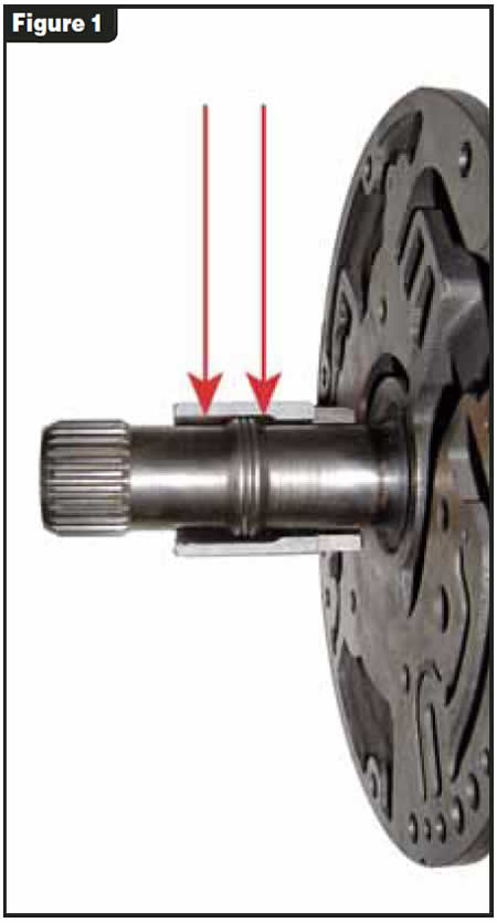
The stator supports of the 400 and TF8 both have a raised area behind the stator splines. The raised area on the 400 measures 1.425 inches, and the raised area on the TF8 measures 1.485 inches. The corresponding 400 and TF8 impeller hubs have I.D. profiles that maintain a clearance of 0.085 inch per side between the I.D. of the hub and the raised area on the stator support. When the hub with the smaller I.D. (400) was mated to the stator support with the larger-diameter raised area (TF8), the converter charge oil was restricted. It was easy to see why the minimal clearance between the hub and stator support would restrict oil flow (see Figure 1).
The mystery of why there was low charge oil going to the converter was solved, but the real mystery was just beginning. The transmission rebuilder understood what had happened to cause the poor converter charge. He reasoned that if making the area between the hub and stator support smaller by installing a smaller-I.D. impeller hub restricted charge oil, then making this area larger would help converter charge. So the next time the transmission was removed from the vehicle, the raised area on the stator support was machined off, removing any possibility of a restriction.
The only problem was that the charge oil did not increase as a result: In fact, it decreased.
Why would decreasing the area of flow and increasing the area of flow both result in less converter charge oil? To solve the mystery you must have an understanding of the relationship between the orifice created between the raised area of the stator support and the impeller hub, and the balance port of the pressure-regulator valve.
When the PR valve is at rest, it is in the high-pressure position. When the engine starts, the pump begins to create pressure (line pressure). This pressure moves the PR valve against the opposing spring pressure and opens the port for converter fill (charge oil). Any time you raise baseline pressure – whether by installing a stronger spring or turning in on the EPC base adjustment – the PR valve will move to a higher-pressure position and the converter charge port will be smaller.
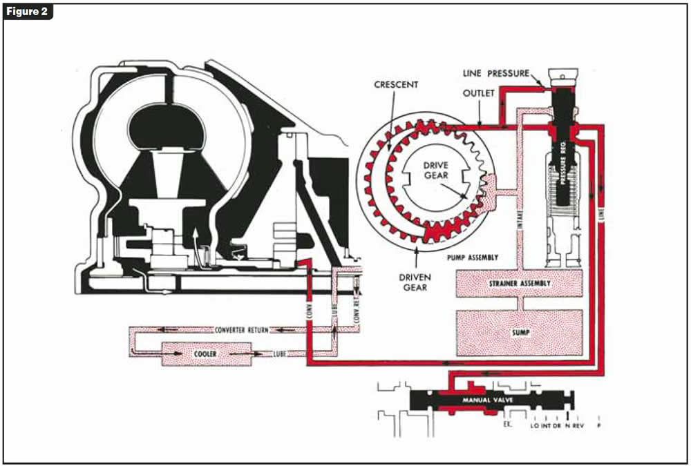
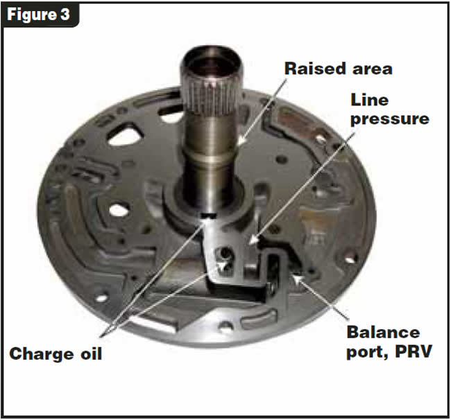
In the transmission field it is universally accepted that enhancing line pressure slows converter fill. If you consider the effect the PR spring has on converter charge oil, it is easy to see how the balance oil on the opposite end of the PR valve also could affect converter charge. Looking at the oil chart in Figure 2, you can see how the raised area of the stator directly affects the balance of the PR valve, keeping it in the maximum-fill position. If you look at the proximity of the components in Figure 3, it is even easier to understand.
Converter charge is different on the non-lockup vs. the lockup, so the complaint will differ. On the non-lockup converters, the I.D. of the impeller hub is critical for converter charge. On a lockup converter, the charge/release oil must enter between the piston and cover. On some lockup converters TCC apply oil passes between the hub and stator. On these converters the hub-to-stator restriction/orifice controls how fast the apply oil enters the converter. In either case the impeller-hub I.D. should not be looked at as just a clearance issue. It is much more important.

Ed Lee is a Sonnax technical specialist who writes on issues of interest to torque-converter rebuilders. ©Sonnax 2006


