TASC Force Tips
- Author: Robert Moreau
- Subject Matter: Honda/Acura units overheating
- Issue: OE tolerance between bore & valve
Most transmission technicians are aware of the notorious loss of proper converter feed that plagues various Honda transaxles. For those who are less familiar, converter charge oil is cut because there is not enough pump output to keep the pressure regulator valve in the regulating position, allowing the TCC to drag and eventually disintegrating the lining. Many technicians have already learned the importance of installing a modified pressure regulator valve during overhaul that ensures converter charge pressure is available at all times, regardless of pressure regulator valve position.
But there is another common issue that remains a mystery to many, and that is overheating. A familiar Honda/Acura scenario begins with a customer describing driving up a long grade on a hot summer day, then suddenly noticing a cloud of smoke in the rearview mirror.
Transmission overheat caused oil to force its way out through the vent, resulting in a smoke bomb as the oil burned off the hot components it contacted. In some cases the fluid gets low enough to cause a neutral-out condition.
This could be a new customer, or it could be someone who was recently in the shop for other transmission repairs. Either way, most technicians begin the hunt for the cause of overheat by focusing on the heat exchanger. Some – thinking there is a restriction – will replace or bypass the existing cooler. Others will “double up,” adding another cooler in series in an attempt to quench the fire. While this can help if there is an actual restriction, it usually does not improve the situation and can even make it worse.
How can adding a cooler make it worse? When monitoring cooler flow with a flow meter under various driving conditions, it may be a surprise to see the flow rate decrease during partial or full lockup after a cooler has been installed in series with the original one.
Obviously the volume of fluid into the converter has not changed, so why is less of it coming back out? Sure, the restriction to flow raises slightly and causes cooler head pressure to increase when adding a second heat exchanger, but not enough to open the bypass and dump fluid volume. Something else has to be going on here.
It can be puzzling and frustrating, especially since it often takes a fair amount of time before the vehicle is driven again under the same hard conditions that caused the original overheat. Quite often you have to wait until the next summer before the vehicle is driven under similar conditions – usually during a family vacation – before finding out that your well-intentioned cooler modification did not prevent the issue from sidelining your customer again. At this point, you have ensured plenty of flow to the converter from the pump and you have increased the heat exchanger capacity, so what gives?

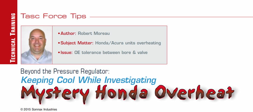
To figure this out, let’s get familiar with the hydraulics related to lockup and cooler function. First we have partial lockup, in which the computer ramps up the duty cycle of linear solenoid “C” to reduce TCC slip to the desired rpm. Pressure is sent to both the apply and release sides of the converter clutch in this mode. As you can see in Figure 1, linear “C” output pressure (green) works against the combined force of the lockup control valve spring and return oil pressure (orange) to regulate release pressure (purple). In turn the release oil works against the apply-side pressure (red) to control the slip rate of the clutch.
In full lockup (Figure 2), release pressure is simply vented to sump, leaving apply oil pressure acting unopposed against the lockup piston. Apply pressure is maxed out by ramping up the duty cycle of linear solenoid “C.” The linear “C” pressure also pushes the lockup timing valve against its spring, cutting off the flow of return oil (orange) going to the lockup control valve. With no return oil at the lockup control valve and maximum linear “C” pressure, the control valve redirects release oil to exhaust. In this phase the slip rate is zero.
The Root Cause
In both partial and full lockup, converter return oil (orange) will all become cooler oil (light blue) as long as the pressure is not high enough to open the cooler check valve. With this in mind, take a closer look at the design of both the timing and control valves (Figure 2). Notice the OEM ran the converter return oil (orange) right next to exhaust ports. If there is too much clearance – aka wear – between the valve spool and the bore, oil that was destined for the cooler ends up leaking right back into the sump instead of going out to the heat exchanger. If you add a second heat exchanger in series, the additional resistance to flow and slightly elevated cooler head pressure pushes even more of the fluid past the valve spools to exhaust. Higher pressure at this unintentional fluid-escape route is why volume often suffers with a second cooler.
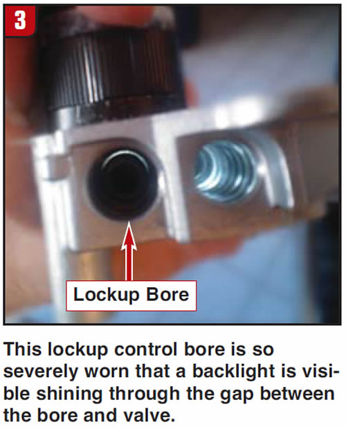
Now that we know which bores to target, further inspection is necessary. It is not uncommon to run into lockup timing and lockup control bore wear that is severe enough to spot visually. Figure 3 shows a backlit lockup control bore; notice the large gap between valve and bore. It is no wonder so much of the converter return oil never makes it out to the cooler with wear that bad. This does not mean the bore is okay if you can’t see past the valve – not all of them are as worn as the one in Figure 3. For the majority of castings, vacuum testing is necessary to prove or disprove bore-sealing ability.
Some Hondas – especially SUVs – are prone to overheating even when new, if driven under extreme heat and load conditions. Since we are talking about a new vehicle, it is logical to assume that the lockup timing and lockup control valve bores would be nice and tight. But as it turns out, the OE tolerance between the bore and valve for these two lineups is quite sloppy.
During vacuum testing of both used and brand-new regulator bodies to assess how much of a problem this was across the board, some interesting results came to light. On average, the lockup timing and control valve bores in random used castings pulled only 10.5 in-Hg of vacuum, a low number that indicates excessive valve-to-bore clearance. But when testing new, unused castings, the average vacuum was only slightly better – 13.0 in-Hg – than the used castings! Thirteen is an unacceptably low number, even if we were talking about a used casting. After reconditioning the bores in all samples and installing oversized valves, a robust 21 in-Hg indicates a successful repair.
This helps explain why Honda/Acura transmissions are so prone to overheat, as the accumulated wear aggravates a poor tolerance issue that was already there from day one.
Once the excessive clearance has been addressed with oversized valves, the cooler-flow difference is like night and day – with no more overheating and fluid blowout under any driving conditions.
Robert Moreau is a Sonnax technical specialist and a member of the Sonnax TASC Force (Technical Automotive Specialties Committee), a group of recognized industry technical specialists, transmission rebuilders and Sonnax Industries Inc. technicians.


