An understanding of hydraulics is essential for correctly diagnosing and repairing transmission problems. This article is part of a series from Sonnax exploring how valves and hydraulic circuits work and what results when they quit functioning correctly.
Later model transmissions control shift apply and feel by using clutch regulator valves, their actuators, and often, an accompanying valve controlling bias (balance) pressure. The components all take their directions from the transmission control module (TCM), which uses inputs (throttle position, speed sensors, etc.) to assess driver demands and conditions to determine how quickly to set the shift patterns.
Using the GM 6L80 as an example, we can see how these shifts occur. Understanding how the components function, diagnostics of a related shift complaint (harsh or slide shifts, slips and flares, delayed engagements, solenoid codes, burnt clutches) can help pinpoint places in the valve body to look for excess wear, sticking valves, or failed electronics.

Examining how a 2-3 shift is made in a 6L80 shows the basics of clutch regulator valve operations and some various designs that are utilized. Figure 1 shows the vehicle in 2nd Gear.
The variable feed solenoid (VFS) is commanded by the TCM to direct fluid pressure (PCS26CL) to the 2-6 clutch regulator valve. The solenoid will ramp up current flow to increase this pressure based on driver demand. The fluid pressure flows against and through the 2-6 gain valve to stroke the 2-6 clutch regulator valve against the spring force, thus opening the passage for clutch feed pressure (from manual valve) to be directed through the valve to apply the 2-6 clutch.
A portion of this fluid pressure is also directed to the inboard (balance) side of the clutch regulator valve to provide some help to the spring to ensure that the apply pressure is regulated to a specific PSI established by GM. If there is wear in the bore, this pressure can be lower or higher than required for proper clutch apply, resulting in the various shift complaints associated with 2nd Gear.
Because this valve is also used in 6th Gear, similar shift complaints would also occur in 6th Gear – helping you narrow down places to look during
your diagnostics.
Figure 1 also shows a clutch regulator valve design variance: the addition of a gain valve. In 6th Gear, the addition of 456CL pressure is added to the 2-6 gain valve, which reduces the amount of fluid pressure acting to push the 2-6 clutch feed pressure valve to the applied position. This provides better control of the 5-6 shift. Another feature often included in clutch regulator valve circuits is the pressure switch circuits. Fluid pressure is sent through the clutch regulator valve when in the released position to apply a pressure switch. The TCM has confirmation of the valve and presumably clutch position.
Figure 2 shows the vehicle in 3rd Gear – so the 2-6 clutch is released, and the 35R clutch is applied.
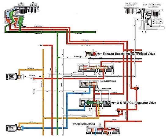
Likewise, the related VFS solenoids PCS4 and PCS 2 are de-energized and energized, respectively. The 35R clutch regulator valve design has a slightly different design variation that is common. As the PCS35R CL pressure strokes the valve inboard, this opens the passage for 35R feed pressure to flow through the valve and apply the 35R clutch. A portion of this oil pressure is also directed to the 35R clutch boost valve, which is also being actuated by the #2 pressure control solenoid. This boost valve directs limited 35R clutch feedback pressure to the balance side of the clutch regulator valve, which helps control the ramp-up of the 35R clutch. So wear at these clutch boost valves can directly impact shift feel related to that particular clutch circuit.
Figure 2 also shows another typical circuit on later model transmissions associated with clutch regulator valves: the use of exhaust backfill. As an apply component is released, instead of simply dumping all of the apply pressure to exhaust, a portion of the fluid will remain in the circuit via the exhaust pressure backfill circuit.
This pre-fills the circuit, allowing for a quicker apply of the component when commanded. Because fluid left in the apply circuit could create an inadvertent or partial apply of the clutch, a countering pressure from the compensator feed circuit is directed to the opposite side of the clutch apply piston to prevent unwanted or centrifugal apply of the clutch.
Knowing how these circuits work and the slightly different variations that the manufacturers utilize should pinpoint any valve body-related issues responsible for various shift complaints and clutch failures.
Maura Stafford is a Sonnax product line manager for transmission components and remanufactured valve bodies. She is a member of the Sonnax TASC Force (Technical Automotive Specialties Committee), a group of recognized industry technical specialists, transmission rebuilders and Sonnax Transmission Company technicians.


