Leeward Tech
- Author: Ed Lee, Contributing Editor
- Subject Matter: Torque converters
- Issue: The movement of oil
Part 1
Examining the outside of the converter
Most torque converter rebuilders can give a good explanation of how the oil reacts with the internal components of a converter to make a vehicle move. Many of the same rebuilders would be hard pressed to explain how the oil that provides this motion enters and exits the converter.
Why is this important?
The oil that enters and exits the converter is the same oil that produces motion, but its duties are unique and completely separate. This oil must keep the converter full for maximum efficiency, but also must flow in and out at a rate that will maintain a proper temperature and provide lubrication when it returns to the transmission.
How does this work?
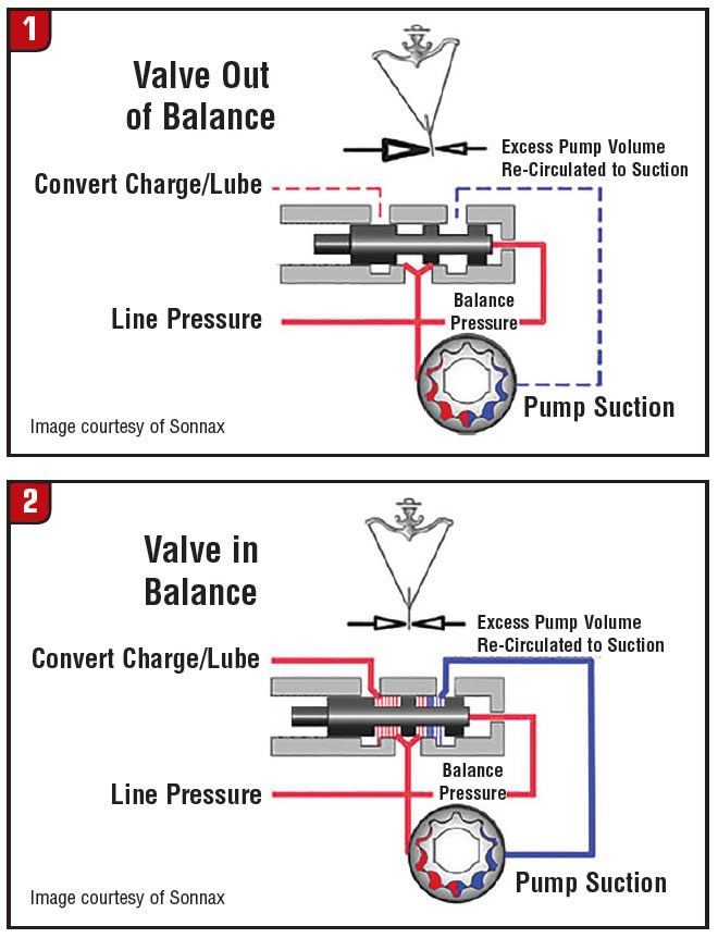
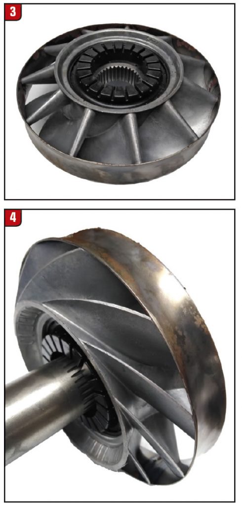
The pump that controls this oil is in the transmission and is in a 1 to 1 relationship with the engine by the way of the flex plate and torque converter. When the engine starts the pump starts providing pressure and this pressure continues as long as the engine is running. This pressure goes directly to the main pressure regulator valve. This valve is a demand valve and its primary function is to maintain the proper operating pressure for the transmission. The secondary function of the pressure regulator valve is to provide charge oil for the converter. At rest, the pressure regulator valve is in the maximum pressure position. (Figure 1)
In this position the converter charge port is shut off. When the engine starts a small portion of the oil from the pump is directed to the balance end of the pressure regulator valve moving it to a slightly lower pressure position. When the pressure regulator valve has moved about 0.070” it opens the converter charge port.(Figure 2)

Under ideal conditions this port remains open as long as the engine is running. Unfortunately, in many instances this does not happen. With the E40D transmission for instance, the combination of wear and low pump volume would cause the pressure regulator to go out of balance, shutting off the converter charge circuit. The result was a stall condition at hot idle when the transmission was put into reverse. The problem was first noticed in reverse because of the increased pressure in reverse. Reverse boost oil would help the pressure regulator spring move the pressure regulator valve to the maximum pressure position, shutting off the converter charge oil. The same issue occurred in the 4L80 converters when the small diesel powerplants were introduced in the utility vehicles. This was caused by the lower idle RPMs of the small diesel engines. The slower RPM caused lower volume, resulting in the out of balance pressure regulator valve.
A similar engine stall condition occurred with the early Chrysler lock up converters and later with the JATCO RE5 converters when the coolers became restricted. The restricted cooler flow leaving the converter slowed the flow of charge oil that would normally float the lock up clutch, in the TCC release mode, allowing it to contact the cover.
A combination of low volume, increasing load and temperature caused a similar condition with the Honda and Acura converters. With these converters when the pressure regulator valve went out of balance, the decrease of charge oil caused the TCC clutch to drag at the hot idle and over heat the converters. The Honda and Acura’s converters did not stall the engines because they do not use the common in and out “2 path” system to control lock up. They use a 3 path lock up system that incorporates a bypass valve similar to the system used in some of the front wheel drive Fords.
All of the above conditions can be addressed by installing a pressure regulator valve that has a “line to charge oil bypass circuit.” With this type of pressure regulator valve, it is also necessary to have a one-way check valve to prevent converter drain down when the engine is not running. There have been many attempts to create a line to charge oil circuit, by drilling a passage through the worm track, but all have fallen short because of the lack of the one-way valve.
The early BorgWarner transmission, i.e. MX, FMX, T35, and T37 to name a few, had a separate converter regulator valve. This valve worked with the main pressure regulator valve to control the pressure with in the converter. This valve regulated the pressure inside the converter to about 40 psi. Today, both of these functions are performed by the main pressure regulator valve and the converter pressures are about two times as high as the early converters. The increase in pressure was necessary for the extra clamping force needed for the lock up converters. From the pressure regulator valve, charge oil travels to the stator support where it enters the converter.
Remember that the earliest automatic transmission did not have torque converters. The torque converter came into being when the stator was added to the fluid coupling. (Figure 3)
With the fluid coupling there was not need for a stator support and oil was free to travel fairly unrestricted between the fluid coupling and transmission. This was not an issue because there was no stator to create heat.
Imagine the challenges that the engineers faced when they were given the task of creating a separate in and a separate out passage for the converter. These passages had to exist within the I.D. of the impeller hub and had to work around an immovable object (the stator support). (Figure 4)
The task was even more difficult when the path of the oil had to change when the lock up was added and again when the third circuit was added for the clutch pack type converters.
Part 2 will cover the flow and regulation of flow inside the converter and the problems created by little changes to the converter.