TASC Force Tips
- Author: Maura Stafford
- Subject Matter: GM 4L60
- Issue: Accumulators and smooth shifting
“Thuds,” “clunks,” “bangs,” “slipping” and “harsh” are all common words used by customers to describe unpleasant shift feel. These complaints can be on upshifts, downshifts, specific gear ranges or on all shifts.
Accumulators and their circuits have been used for years as the primary method for controlling shift feel. These components are designed to modify a shift by essentially acting as a shock absorber for the fluid pressure that is applying a clutch, brake or band. Cushioning of this high pressure allows the apply component to engage gradually, instead of slamming on and rattling parts and bones alike.
Through the years, accumulators have changed significantly. Like most other changes, the driving needs were to increase fuel economy, improve shift quality and reduce overall manufacturing cost by maintaining or reducing size and weight of the transmission. In older 3- and 4-speed, fully hydraulic transmissions, accumulator circuits were typically large pistons and springs, with numerous additional valves helping to control pressures and flow. As electronics came into play, solenoids were added to the accumulator circuits, giving better control to the shift feel based on driving conditions, thereby eliminating the need for some valves. In many newer 6- and 8-speed transmissions, “traditional” accumulators and related valves are no longer needed. That’s because the computer and solenoids have direct control over the shifts, providing very fine control of shift feel, often in clutch-to-clutch transitions. Regardless of the transmission design, apply pressure accumulation is still occurring — but the related devices are much more varied. To properly address your customers’ complaint of shift feel, it is important to understand these various components, how they work and typical failure modes and corrections for each.
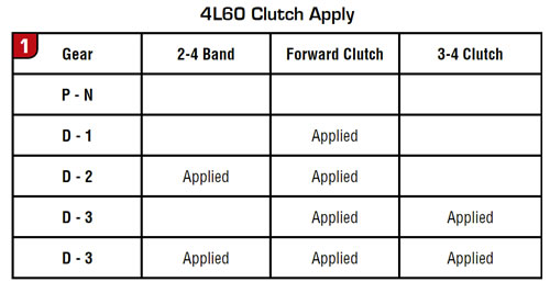
A look at the apply components and accumulator circuitry in a GM 4L60 (700-R4) in D1–D4 ranges will provide a great understanding of basic, fully hydraulic shift feel control. Figure 1 shows a very simplified apply chart showing clutch and band activity, as we focus on how the apply and release pressures are accumulated.

Figure 1 – 4L60 Clutch Apply
As the vehicle is moved from Park to Overdrive, the forward clutch is applied. The manual valve directs regulated line pressure into the D4 circuit (Figure 2), which seats the #12 checkball.
Figure 2 – 4L60 Forward Accumulator Circuit
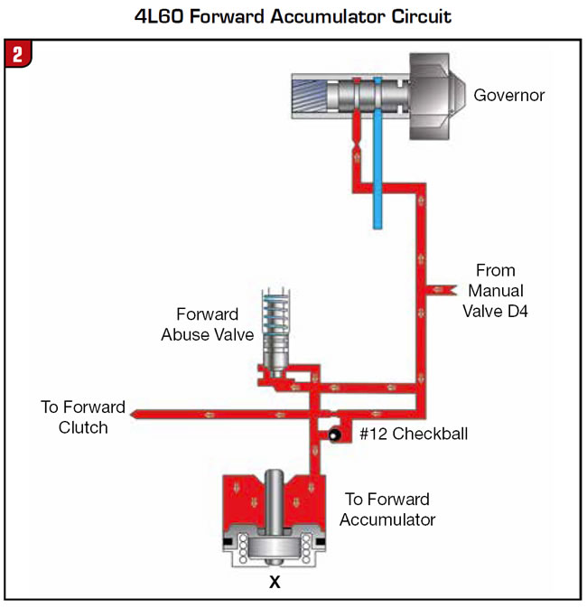
At low pressure/idle, this fluid is forced through the orifice, where it will gradually stroke the forward clutch accumulator piston against opposing spring force, thus absorbing the D4 pressure that is also routed to apply the forward clutch. As throttle pressure increases, D4 pressure will increase and stroke the forward abuse valve against spring force, which allows the orifice to be bypassed and fluid flow to the forward clutch and accumulator to increase for a quicker apply. It is important to have the circuit be throttle-sensitive, as quicker and firmer shifts are desired at higher speeds for improved shift feel, as well as to prevent prolonged clutch slip and heat build-up that reduces clutch life. The forward clutch is engaged for all Forward gears. When manually shifting, the selector from any Forward gear to Park or vehicle would be stopped first. The forward clutch would then release, unseating the #12 checkball for a rapid exhaust of apply pressure. For this same reason, it is not necessary to have the accumulator piston stroke against throttle-sensitive fluid force; spring force alone is adequate. Forward clutch failure or harsh forward engagement could be caused by leakage in the accumulator circuit, most notably at the forward abuse valve bore in the valve body and at the piston-to-pin interface of the accumulator piston.
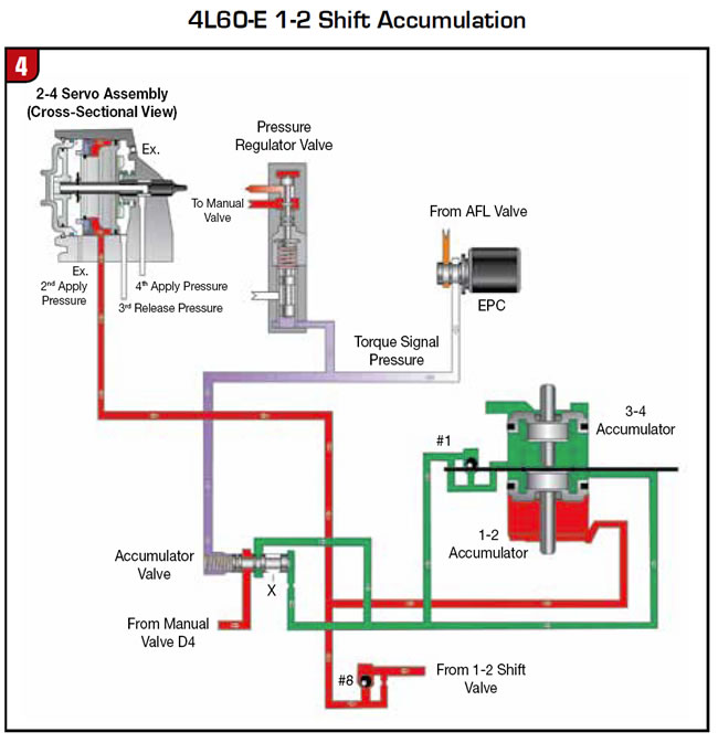
As vehicle speed increases, the shift to 2nd gear will occur and the 2-4 band will apply. Figure 3 shows 2nd fluid being directed from the 1-2 shift valve to seat the #8 checkball, which meters the flow to the 1-2 accumulator piston and the 2nd apply piston in the servo assembly through an orifice.
Figure 3 – 4L60 1-2 Shift Accumulation
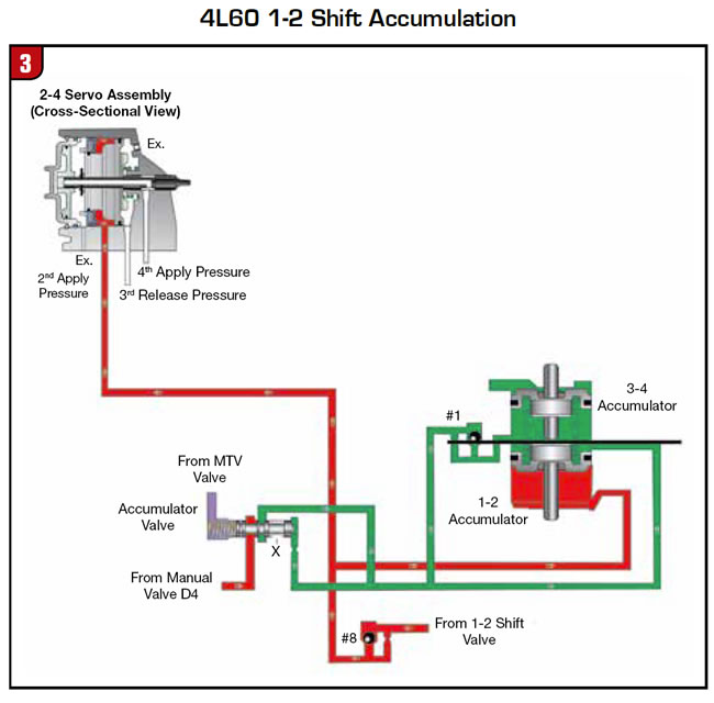
In this instance, the accumulator piston is absorbing 2nd apply pressure by working against a spring and throttle-sensitive fluid force, which is provided by the accumulator valve as it regulates D4 pressure into the 1-2 accumulator circuit. The addition of this throttle-sensitive, 1-2 accumulator pressure helps to better control the shift feel based upon the speed of the vehicle. So, a higher speed will result in greater back pressure to the accumulator piston, which will result in a firmer and quicker 1-2 shift. This accumulator valve has various size ratios from OE to provide different shift feels for various vehicle and engine combinations. Servo assemblies used to apply bands often have built-in accumulator action, as shown in this instance as 2nd fluid strokes the 2nd apply piston against spring force to apply the 2-4 band. This 2nd apply piston also has different OE sizes for various performance shift feels. Concerns with a 1-2 or 2-1 shift feel could be the result of wear at the accumulator valve, 1-2 accumulator piston, servo assembly or pin-to-case wear. The incorrect 1-2 accumulator valve or servo piston ratio can also create undesired 1-2, 2-1 shift feel.
The 4L60-E transmission basically kept the same transmission architecture as the 4L60, but introduced various electrical devices that controlled pressures based off of various inputs. The same accumulator and servo piston components are still used on the 4L60-E as on the 4L60, and the same simplified apply chart for the 2-4 band, Forward and 3-4 clutches in Figure 1 can be used. The 4L60 primarily used a mechanical governor assembly for determining vehicle speed by engagement with the output shaft. Throttle pressure adjusted by a mechanical lever connecting the gas pedal to the throttle plunger valve to control the pressures associated with shift timing and feel. This also required numerous support valves (throttle valve, MTV downshift, MTV upshift, TV limit, line bias) to fine-tune the shift control based on driver needs. The 4L60-E eliminated these valves, the governor assembly and mechanical throttle controls by accomplishing the same functions with an EPC (electronic pressure control) solenoid (Figure 4) controlled by the power control module (PCM) getting inputs from speed sensors and a throttle position sensor.
Figure 4 – 4L60-E 1-2 Shift Accumulation
This switch to indirect electronic control also provides greater precision in timing and shift feel by allowing real-time monitoring (via speed sensors) of the vehicle speed so that instant changes can be made to accumulator circuit pressures to adjust the shift feel mid-shift. On-off shift solenoids were added, allowing the ability to schedule shift changes via the PCM, which could be tailored to the type of vehicle, engine, driving conditions (incline, temperature, altitude, etc.) and driver demands. So in addition to the previously noted hydraulic accumulator and valve components causing shift feel complaints when worn, add faulty solenoids, sensors and the PCM itself to the list when performing diagnostics and determining root cause.
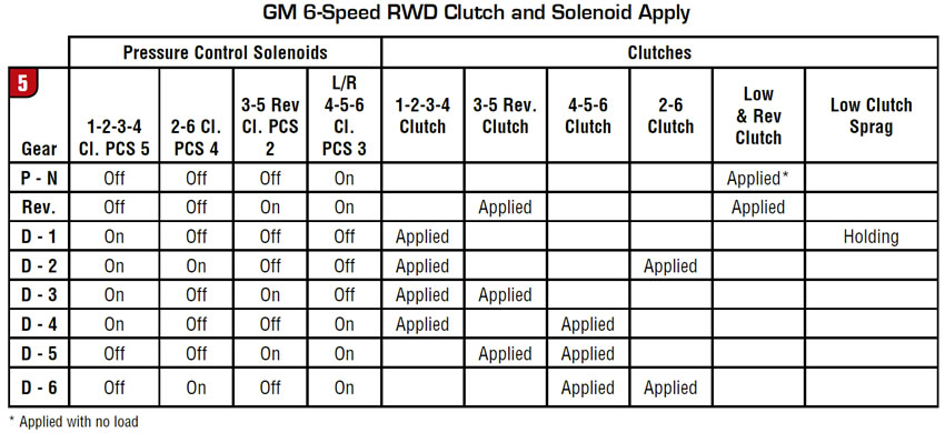
In 2006, GM introduced the 6-speed series of RWD units: 6L45, 6L50, 6L80 and 6L90. Like other GM transmissions, the last two digits indicate the relative torque of the unit, with the higher numbers having increased torque capacity for higher performance applications. While some internal hard parts vary between these torque ratios, GM was able to keep the hydraulic valves and calibrations the same. These units do not have a single “traditional” accumulator or servo piston in the circuitry. The shifts in these units are clutch-to-clutch (Figure 5), which helps to control the size and cost of the transmissions.
Figure 5 – GM 6-Speed RWD Clutch and Solenoid Apply
- Applied with no load
This design and shift architecture is made possible by the further improvement in computerized and electrically controlled shifts. By utilizing direct acting pressure control solenoids (PCS), sophisticated programming and algorithms for shifts based on a multitude of driver and environmental inputs and adaptive-learning processes, shift timing and feel can be controlled very tightly and literally with each and every shift. This type of technology allows for shift timing and feel adjustment as internal hard parts and clutch components wear that — in fully hydraulic or indirectly controlled transmissions — would have resulted in undesirable shifts. This can further extend the service life of the transmission and its components.
It is important to understand the details of how these shifts occur, as there are still components in the circuitry that can fail and lead to shift feel complaints. The various clutches have designated pressure control solenoids, which, via commands from the transmission control module (TCM), directly modulate actuator feed limit pressure into PCS clutch pressure. This PCS clutch pressure is then directly applied to a clutch regulator valve and clutch boost valve (except for the 2-6 clutch), which routes the clutch apply pressure directly to the clutches. This allows the TCM to directly control apply and release pressure at the various clutches based off of the various driver and environmental inputs. Figure 6 shows an example of this, as the 1-2-3-4 clutch begins to apply.
Figure 6 – GM 6-Speed RWD 1-2-3-4 Partial Clutch Apply
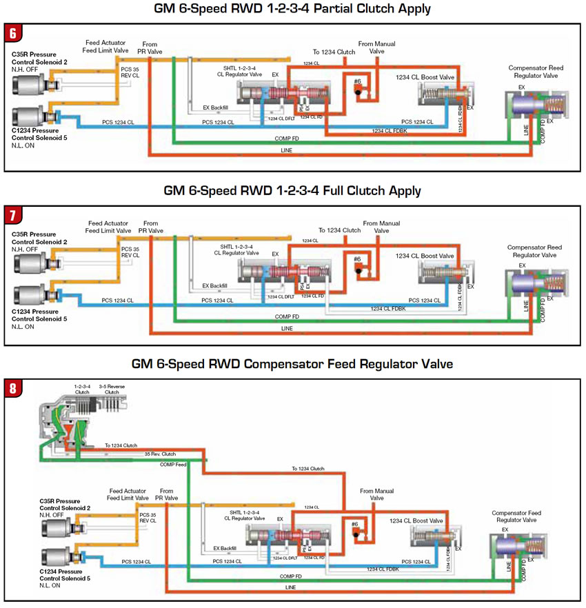
PCS 5 fluid pressure is directed to both the 1-2-3-4 clutch regulator and 1-2-3-4 clutch boost valves. As the clutch regulator valve strokes against spring force and clutch feedback pressure, clutch feed pressure is regulated into the 1-2-3-4 clutch and it begins to apply. As PCS 5 fluid pressure increases (Figure 7), the clutch boost valve will stoke completely, opening clutch feedback pressure to exhaust and allowing full stroke of the regulator valve so that full clutch apply pressure is sent to the clutch.
Figure 7 – GM 6-Speed RWD 1-2-3-4 Full Clutch Apply
Thus, by the TCM controlling the PCS, a gradual pressure is applied to the clutches through the valves, which aids in controlling shift feel. The TCM also monitors the input and output speed sensors, and as clutches and components wear, “adapts” and changes PCS output pressure to compensate and maintain proper shift timing, overlap and feel. So, wear at the clutch regulator valves or clutch boost valves could exceed the parameters of what adaptive learning compensates for, and poor shift feel and timing could occur. Likewise, wear at the actuator feed limit valve or dirty/faulty solenoids could cause these complaints.
A valve that is tied into the 1-2-3-4, 3-5-Rev. and 4-5-6 clutch apply circuits that can greatly influence shift feel is the compensator feed regulator valve. This valve (Figure 8) regulates line pressure into the compensator feed circuit to hydraulically assist clutch return springs during release of the rotating clutches.
Figure 8 – GM 6-Speed RWD Compensator Feed Regulator Valve
After the clutches disengage, the compensator feed circuits maintains some pressure in the clutch release cavity to oppose centrifugal application of the clutches. Even during release, the clutch apply cavity retains fluid through the clutch exhaust backfill circuit, which is fed by clutch oil through the clutch regulator valves as they exhaust during release. In clutch-to-clutch apply applications, timing is critical, so maintaining some residual oil pressure in both the clutch apply and clutch release cavities of a clutch will allow it to essentially be primed for quicker action when commanded.
As transmissions continue to add speeds, new and creative ways for controlling shift timing and feel are being developed. GM’s 8-speed RWD unit seems to be heading in the direction of more sophistication in the adaptive controls by programming based on each individual PCS’s flow characteristics. So, while traditional, “hydraulic” accumulators were a primary source of shift feel, it is important to look beyond those components to address shift complaints in newer transmissions.


