The function of most manual valves in automatic transmissions is the physical connection from the driver to transmission range selection. This connection has morphed from steel linkage arms to shift cables and now full electronic control called “shift by wire.” This physical connection makes it possible for the driver to select a Drive shift position for forward motion, a Manual position for manually shifting or for limiting gear shifts in a Forward range, a Reverse shift position for backing up the vehicle, and a Park position for starting/shutting off and exiting the vehicle.
Manual valves operate in a similar manner, but there are many different types. The main function of the manual valve is to connect hydraulic pressure to the clutches or brakes connected to a Forward, Manual shift, Reverse or Park position through the positioning of shift and/or regulating valves. Figure 1 shows manual valve position for the Park, Reverse, Drive and Manual shift positions for the 6L80 family of transmissions.
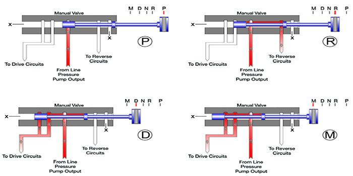
Notice in the Park position, the line pressure is blocked by the rear valve spool of the manual valve. When Reverse is selected, the manual valve is moved over to the Reverse position by the driver, and line pressure is connected the Reverse oil circuits. When Drive is selected, the driver moves the shifter to the Drive position, and the manual valve is moved to the left to connect line pressure to the Drive oil circuits. Figure 1 shows the connection to the manual linkage on the right that lines up with the PRNDL selection, and those familiar with the 6L45 in BMWs who have seen the end broken off understand the complaints related, as in stuck in Drive or a no-engagement condition. This would make perfect sense, as the two spools of the manual valve would be stuck where they were last, when the end broke off. Another function of the manual valve is to provide an exhaust path for the Reverse oil circuits when it is moved to the Drive position. Figure 1 also shows the manual valve in the “M” position or Manual shift position. Notice there is not much of a function here, as the Manual shift mode on the 6L80 transmission is handled through electronic controls. When the shifter selects the Manual position, the internal mode switch (which is connected to the manual valve) tells the TEHCM that the Manual shift position is enabled. At that point, the driver can select gears manually through the “+” or “–“ buttons on the shifter handle. Seeing the circuitry associated with manual valves, it makes sense that these valves can create numerous complaints related to low pressure and/or delayed engagements, which could cause premature clutch failures and associated diagnostic trouble codes. Vacuum testing these types of valves is also important, as pushing the valve side to side can also help to ensure that the bore is in good shape. Manual valves typically have a little more bore clearance and lower readings than regulating valves, so it is important to record and compare test results when vacuum testing.
Electronics have impacted the transmission industry in a big way. For example, the Chrysler RFE family saw a change in late-2010 production that impacted the manual valve hydraulic circuit, when the Manual 2 and 1 positions were removed from the shifter. Figure 2 shows the RFE manual valve oil circuit.
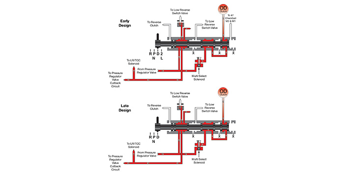
The top illustration shows the previous design of the manual valve oil circuit that started back in 1999. Note that on the top illustration, the PRNDL positions include Manual 2 and L positions that the driver can select. When the valve is put in that position, pressure will be connected to the #7 checkball, which feeds the Manual 2 and 1 circuits. On the bottom illustration, note that the Manual 2 and L positions are gone and the passage to the #7 checkball is no longer there, as the separator plate was changed and the #5 and #7 checkballs were eliminated. This shifter change not only changed the manual valve function, but also changed the solenoid pack assembly, and the grey connector was introduced. This newer design of the solenoid pack assembly does not have the Overdrive solenoid in it, and the shift control strategy in the PCM changed to accommodate the hydraulic changes.
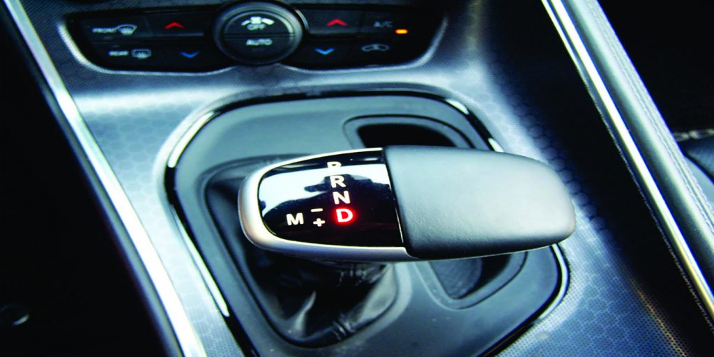
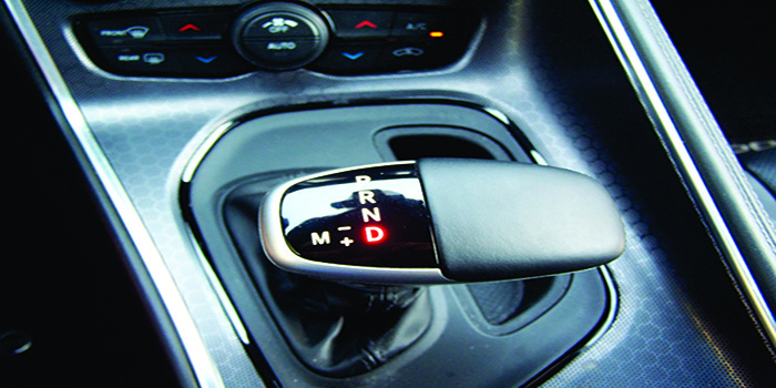
In some instances, vehicle manufacturers have taken the mechanical control away from the driver, via linkage arms and shift cables, and have put it into an electronic motor that rotates the internal linkage which changes positions of the manual valve based on driver input to a rotary shift knob or a shifter assembly. This is referred to as “shift by wire.” Other vehicle manufacturers have eliminated the manual valve altogether and electronic controls are completely responsible for routing pressure to clutches or brakes connected to a Drive, Reverse or Park position. BMW was one of the first manufacturers to introduce this all the way back in 2001. It was referred to as “E-shift.” The driver still selects which shift strategy, whether it be Forward or Reverse motion or Park position, but the electronics take over and control application of ranges from there. This “E-shift” control strategy can be also found in most ZF8HP applications in Chrysler, Ram, BMW and many other import rear- and all-wheel drive vehicles. Figure 3 shows a view of the shifter mechanism on a Dodge Challenger equipped with a ZF8HP45.
This shifter has no mechanical connection to the transmission. Figure 4 shows a cable that is connected to the transmission, but is only used for a towing situation.
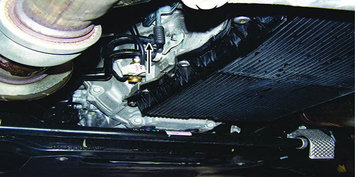
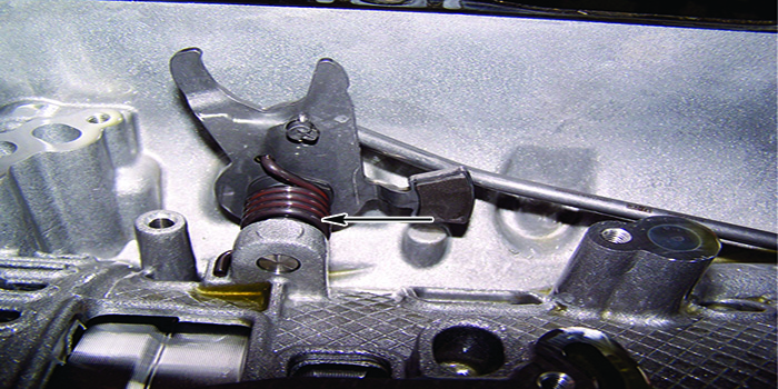
The reason for this cable is to have an emergency Park release because the Park pawl, in this type of transmission has a spring that loads the park rod in the Park position as shown in Figure 5.
Figures 6 and 7 show the lower valve body on the ZF8HP45 and the location of the two solenoids that control Park release.
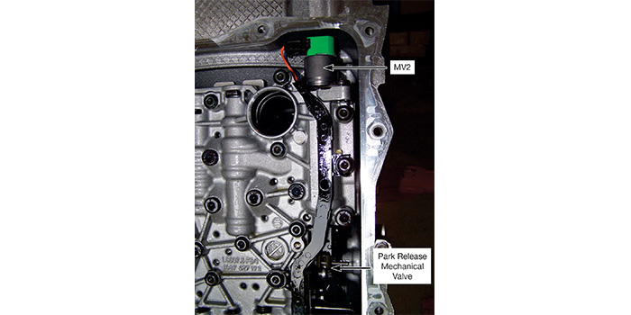
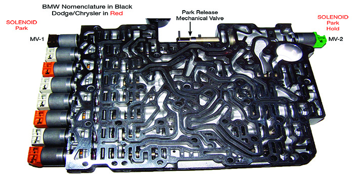
MV-1 is on the left and MV-2 is on the right. These two solenoids control the release of the parking pawl. MV-1 is energized, which strokes the park pawl release valve. That sends pressure to the park release mechanical valve, which strokes the park release mechanical valve towards MV-2 solenoid which, when energized, retains the park release mechanical valve, keeping the parking pawl released. A capable scan tool is a must for diagnosing these types of systems, as a no-engagement condition can be as simple as someone spilling a cup of coffee into the shifter.
In summary, manual valve and/or manual valve control still (in theory) have the same function, but have undergone some major changes to accommodate some of the new features, such as hands-free park assist, that this wonderful world of electronics that we live in has to offer.
Jim Dial is a Sonnax technical specialist and a member of the Sonnax TASC Force (Technical Automotive Specialties Committee), a group of recognized industry technical specialists, transmission rebuilders and Sonnax Transmission Company technicians.


