R&R Tech
- Author: Carmen Klaber
- Subject Matter: Diagnosis
- Vehicle Application: 2005 Toyota Camry
- Issue: Shift problems
Those of us who worked on vehicles that predated mandated catalytic converters and gas shortages can remember a wonderful time when even the most-complex electrical systems could be diagnosed with a simple test light. Computers were just starting to transform from behemoths that took up entire rooms in buildings to something that could actually fit on your desk. And there were only four wires connected to the transmission. Yes, youngsters, I said four. Those were the days.
As with all things, change is inevitable. In the realm of technology, along with change come added layers of complexity. Modern technicians see this complexity every day, along with the challenges that come with it in regard to diagnosing vehicle issues that bring customers to our doors. Enter the subject of our story: a 2005 Toyota Camry with a shifting concern.
While verifying the customer’s concern during a road test, we noted second-gear starts with no perceivable shifts, and the Check Engine light (CEL) was on. After we got the car into the shop, the fluid checked OK and the scan tool revealed codes P0748 (SL1 electrical fault) and P0778 (SL2 electrical fault). Since these were electrical codes for the shift-solenoid circuits, we would expect to find an issue with the solenoids themselves, the wiring to them, grounds or, in some instances, the ECM (engine control module).
The first thing we needed to do was to clear these codes and see whether we could recreate the concern. After we cleared the codes, the transmission shifted through the gears just fine. As we took off from the second stop, however, the CEL popped on and the transmission forced a second-gear start. As expected, when we pulled the codes again, we had the same codes as before. It was time to get out the DVOM and see whether we could find out what was causing the issue.

Starting at the solenoids, we verified the resistance to be within the 5.0- to 5.6-ohm specification. The solenoid connectors looked clean and dry, so no reason to suspect problems there. After plugging the connectors back in, we moved the DVOM to the ECM connectors. We needed to check the integrity of the rest of the circuit.
On this particular vehicle, the solenoids are both powered and grounded via the ECM. This is not true for all vehicles. The benefit for testing purposes lies in the simplicity of the circuit. As long as we have good grounds to the ECM itself, any circuit issues generally can be traced to the wiring between the ECM and the solenoids. On this car, all the solenoid wiring runs through the E9 connector at the ECM.
We disconnected both the E9 and E10 connectors from the ECM for testing. The E10 connector contains several ground wires for the ECM, and those passed testing with no issues. This was to be expected, since any problems with these grounds would more than likely have created issues with other controlled components as well and resulted in additional codes. E9 also contains grounds in addition to the solenoid wiring itself. Those grounds also checked out OK.
With the battery disconnected, the resistance through each solenoid was within specification when tested from the E9 connector. That told us that the wiring had no opens between the ECM and the solenoids themselves. We also checked for any shorts between each of the wires to ground and power and found none. All resistance checks passed, and it would appear that the integrity of the wiring was good.
At this point, one could say that the circuit passed all testing and we could begin looking elsewhere. If you’ve been doing this kind of work long enough, then you know that that the resistance checks test the integrity of the circuit only marginally. Sure, the wiring is intact per our testing, but can the wires carry a load? This is a question that must be answered for any circuit that supplies a component with voltage.
The easy way to test this is to use a headlamp bulb wired in place of the component, and in this instance that would be our solenoids. I caution that we are only testing the circuit; the ECM is still disconnected at this point, and we will be providing voltage directly from the B+ terminal of the battery, and a solid grounding point. This will check the ability of the circuit to carry a load.
A bright light shone for each of the solenoid circuits tested. That meant that the circuits were indeed intact. Rats! We have to keep looking.
To recap thus far: The solenoids tested OK, as did the circuit and associated power and ground supplies. We now suspected that the ECM might be faulty, but we needed to make ourselves more comfortable with condemning it before we went to the customer with a recommendation.
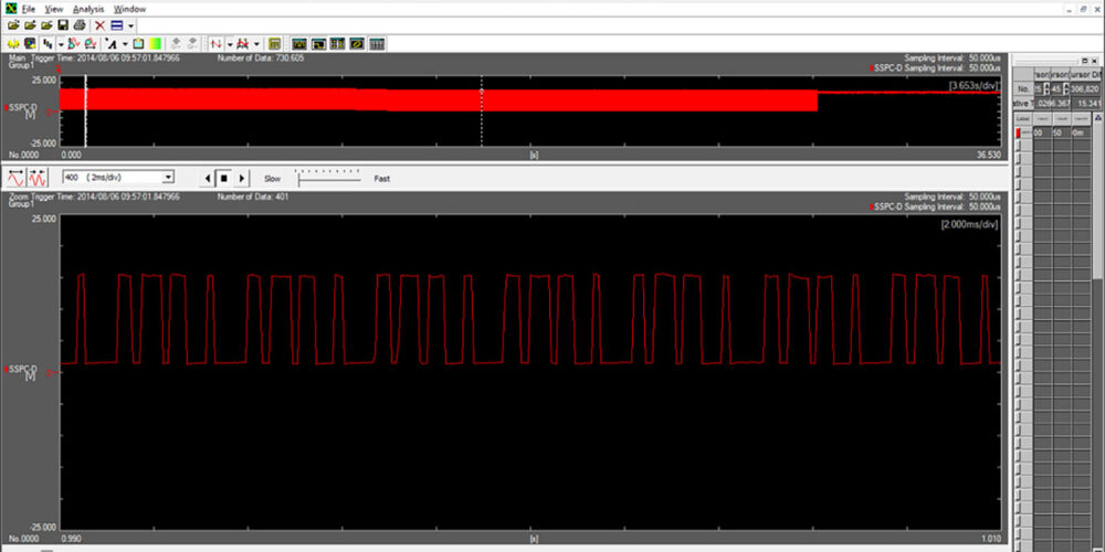
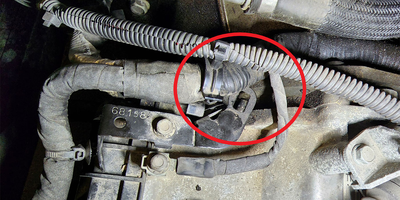
One last trick in the auto technician’s bag is the all-important, often-omitted “wiggle test.” Your kids might just giggle at such a statement. However, in a world of intermittent issues, this test must be performed on every connector and wiring harness involved in the circuit we’re chasing. We would need to grab these items while the solenoids were activated to see whether we could capture a problem with them.
With the solenoids activated, we did just that. When we wiggled the E9 ECM connector, we could get the CEL to turn on and codes to set. OK, we’ve pinpointed the location of the issue, but what was causing it? Close inspection of the connector was of little help. We couldn’t see anything wrong with it, and Toyota does not offer a replacement connector for the ECM.
One possibility was connector “pin fit.” Vibration, heat and all the other conditions that these components endure can cause the pins to loosen and create an intermittent connection with the component it mates to. Running with that theory, we resized the connector terminals by slightly crimping them, creating a better “grab” onto its mating pin.
Misdiagnosis averted. This action solved the issue. When we repeated the wiggle test, we were unable to set the codes or CEL. The loose-fitting pins were creating an intermittent connection and causing the issue. A subsequent road-test confirmed that the vehicle was repaired and ready for the very happy customer to pick up.
It’s easy to see how this scenario could apply to many different circuits. In this instance, we could have easily sold the customer a new ECM. Had we done so, the root cause of the problem might not have been addressed and instead of creating a loyal customer we might have lost one. There isn’t much complexity in that; it’s about as basic as it gets.
Carman Klaber has been in the auto industry for more than 25 years and is also an experienced rebuilder. He is an ASE certified technician and has been with Certified Transmission since 2003.