TASC Force Tips
- Author: Bob Warnke
Some things are less intimidating if you’re not the first to do it. That statement applies to both crossing a frozen lake and working on a problematic AW55-50SN. On the lake, heavy snow cover can prevent you from telling whether the ice is sufficient for support, and what you can’t see may end in a sink-or-swim experience. On the 55-50SN valve body, a clean core does not mean the valve body is functioning correctly.
This material is a route that other travelers have marked past the “thin ice” of the AW family. At these flags, the test or inspection frequently points to a problem in the valve body, as this accounts for the majority of the transmission’s issues. The 55-50/51SN is installed in a multitude of vehicles, and there will be variations to the unit and this data. A similar valve body will bolt to a GM, Volvo, Saturn, Nissan, Saab, Opel or Renault. Failure to test and recognize the differences among them can create hours of additional effort.
Pressure and fill
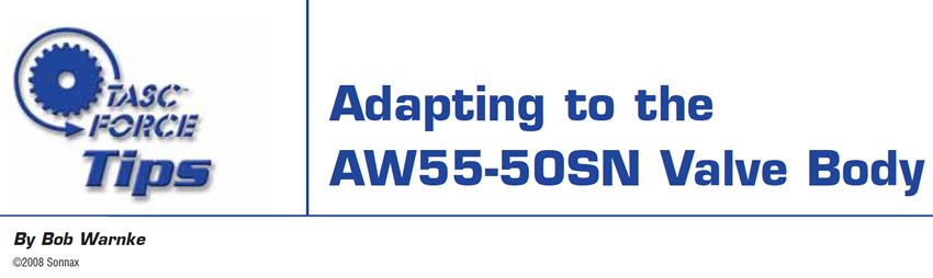
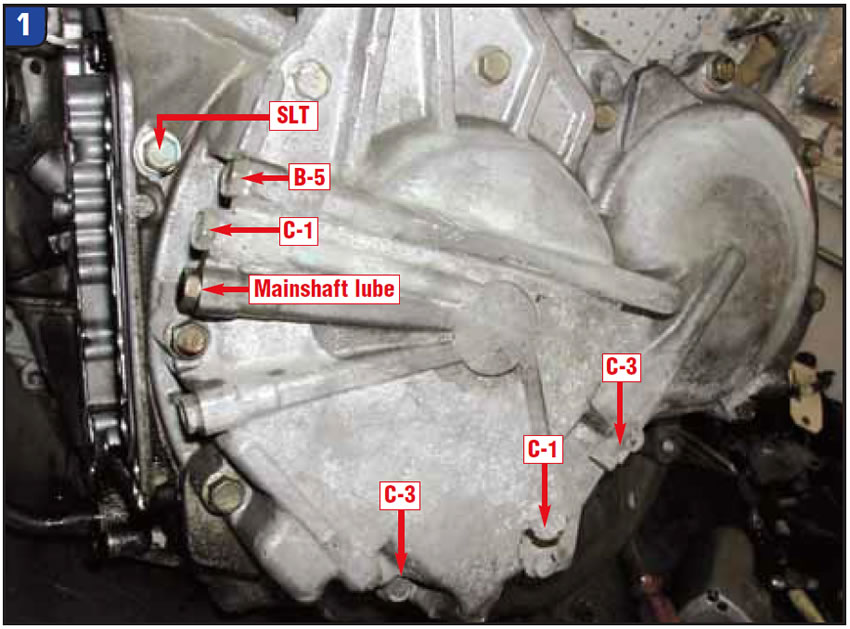
All the pressure plugs have 12mm heads. Do not mistake the 27mm band anchor (see figures 1 and 2) for a fill plug or pressure tap. If that anchor is removed, the band will have to be recaptured. Positioning the band requires removal of the servo at best, and possibly the complete transmission.
The turbine forward-/input-sensor hole can be used to improve the fill speed. Low fluid or excessive overfill can create erratic pressure and poor linear solenoid control, eventually forcing a TCM high-pressure strategy.
If the transmission is in the vehicle, “test the ice” at the pressure taps relative to these complaints:
TCC rpm fluctuation and overheated fluid
Check lube pressure. The lube-pressure tap is between the secondary regulator valve and the main-shaft bushings. Lube pressure will be affected by the fluid viscosity (flow rate) and the bushing-to-shaft clearance. Sufficient pressure at operating temperature indicates the filter, pump and both primary and secondary regulators are functioning. Normal lube pressure at the port indicated: At –10° F, lube pressure can be as high as 30 psi. At 150° F, normal lube will be 5 psi in drive and 8 psi in reverse. This indicates the bushings are in place and can retain some of the source pressure. Lube pressure that starts low and stays at zero psi indicates your pump output is low, the regulator valve bore is worn or your bushings are bad.
If you are diagnosing a TCC complaint, perform a cooler-flow test. Normal flow in drive with TCC released is 1.3 gpm, and during TCC apply it drops to 0.7 gpm. The Saab cooler element will require an adapter, but most units are easily accessible.
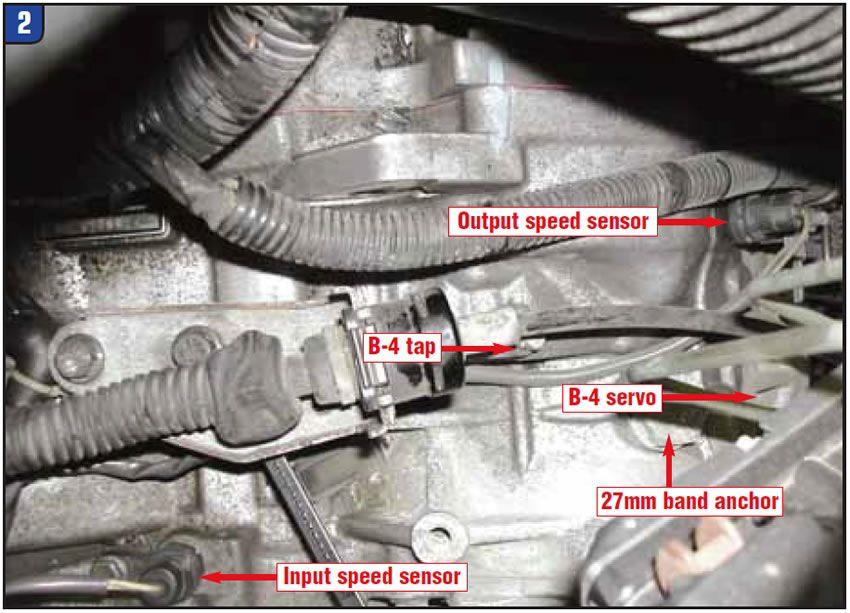
Lube pressure and flow on the 55-50SN are low in comparison with other units. This converter requires multiple valves, along with the rear pump bushing, to control modulated TCC apply (see Figure 3). The converter clutch may remain fully applied at very low speed and high load, which taxes the fluid and lining, creating a break-away slip or rpm fluctuation.
Delayed engagements and poor/flared shifts
Check SLT pressure and the C-1 clutch. The C-1 clutch is engaged via pressure rise by the SLT solenoid and through a series of modulated valves. The SLT pressure should start at 5 psi in drive and increase with throttle and load to 80 psi maximum. SLT will cut back and spike on various shifts, depending on the TCM program.
Typical C-1 pressure is zero in park. As drive is selected, it quickly steps to 25 psi, then 50 psi, within a half-second and remains until the vehicle is accelerated. C-1 pressure will then follow load, with a maximum near 200 psi. If C-1 pressure upon selection of drive is immediately 160 psi and achieves 200 psi during a shift, the unit may be under a TCM-code/failsafe mode. Engagements at this time are abrupt. Some vehicles (Volvo, specifically) may use a C-1 disengagement via brake signal creating a neutral at idle. Check for a TCM flash to eliminate this condition.
2-3 shift flare, neutral or harsh
Compare the B-4 servo-apply pressure with the C-1 clutch. The B-4 tap is at the top of the case, in line with the linkage bolts. The B-4 circuit has extensive valve-body control and includes a tube with O-ring ends that feed the servo. Comparing C-1 with B-4 is an indication of control by the SLS and SLT linear solenoids, a failsafe or leakage condition.
Proper B-4 pressure should follow C-1 and never be less than 10 psi of C-1 (refer to the C-1 pressure testing). If C-1 pressure is fixed at 160 psi on engagement, the 1-2 and 3-4 shifts may be acceptable, but the 2-3 is generally too harsh. A TCM pressure-management code, aerated fluid or a bad speed sensor will eliminate the SLT pressure curve and force B-4 to an immediate 200 psi, which results in the harsh 2-3 shift. If the pressure curves of both C-1 and B-4 are parallel, C-1 initial engagement is near 50 psi and the 2-3 is harsh, the vehicle may require a flash update, but perform a key cycle and numerous drive cycles first. Some manufacturers (Volvo) have servos and a reflash to improve 2-3, 3-2 drivability.
SLT air test
Before removing the valve body from the transmission, you can perform a visual wet air test of the SLT circuit. If you pressurize the SLT port with shop air (80-100 psi), air pressure will push fluid, which you see as a leak. Problematic leaks occur at the steel side cover, SLT accumulator, and B-1 and C-1 control valves. A major leak – or combination of leaks – can cause delayed engagements or flared upshift and should be inspected after disassembly.
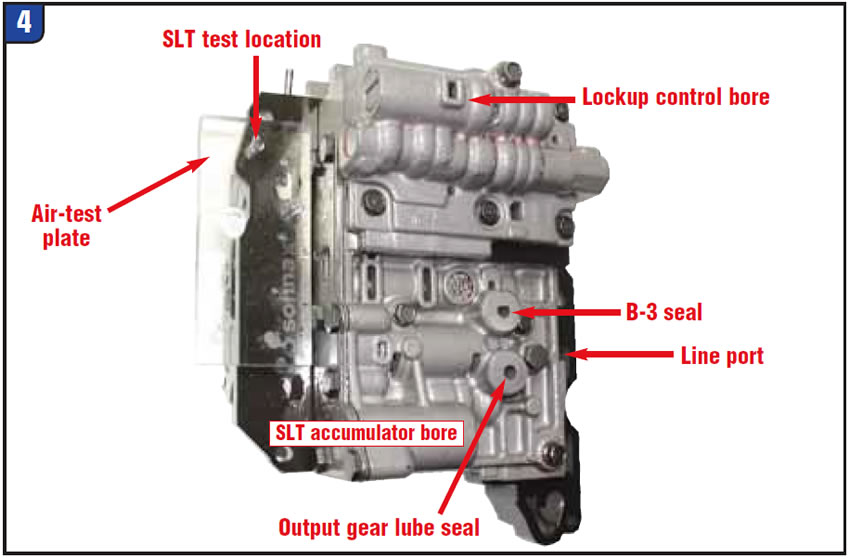
You can perform a similar air test with the valve body itself (see Figure 4). When you’re doing so, the pump line port and thermal-element hole must be closed and the separator plate held as shown to eliminate cross leaks. This might sound confusing in print, but when you do it, the ports will be evident and easy to close with your other hand.
Valve-body inspection
There are many variations, which complicates coring and matching parts. Figure 5 identifies visual changes. Currently there are six different shift solenoids, four of which can be installed in incorrect locations or replaced by a normally open vs. normally closed solenoid. The shift solenoids should be checked for proper flow when open and for sealing when closed. These are fed line pressure from an orifice in the plate and can be over-pressurized.
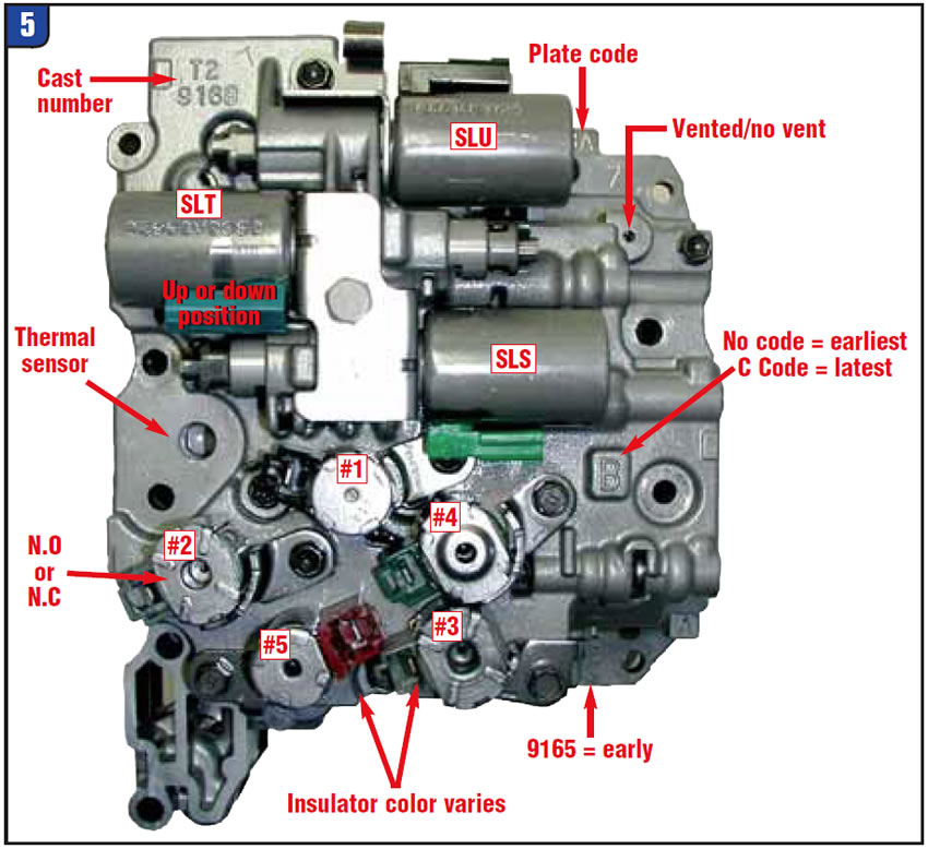
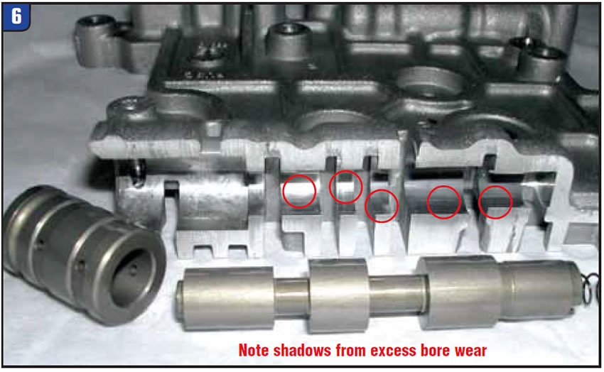
Three linear solenoids are calibrated to the valve body. Exchanging SLT and SLS solenoids between cores without adjusting to the valves is generally not acceptable. Don’t hesitate to open and inspect the valve body, since it’s comparable to other Aisin Warner designs and is not difficult to reassemble. That inspection should include all the removable sleeves, both regulator valves and the solenoid modulator bore. The linear solenoids are fed by this modulator valve, which limits the maximum pressure. When that bore is worn, the concern is similar to a bad GM actuator feed circuit.
Excess wear appears as a discoloration, or polished area, in the shape of a moon phase, generally at the ends of the bore or opposite side of fluid entry (see Figure 6).

Bob Warnke is vice president of technical development and a member of the TASC Force (Technical Automotive Specialties Committee), a group of recognized industry technical specialists, transmission rebuilders and Sonnax Industries Inc. technicians. ©2008 Sonnax


