Shift Pointers
- Subject: Drive and Reverse engagement problems
- Unit: AW55-50SN (Nissan RE5F22A, GM AF33-5)
- Vehicle Application: 2005 Nissan Altima
- Essential Reading: Rebuilder, Diagnostician
- Author: Jesse Zacarias
The AW55-50SN transmission has been with us now for a little more than a decade, and judging by the calls I hear coming to the tech line at Valve Body Pro by people who rebuild their own solenoids, it continues to be somewhat of a mystery to many of us.
I will try to explain one of the most-common questions being asked, concerning Drive and Reverse engagement problems. Some of this information has been covered at the ATSG seminars, so I will be using some amperage and pressure readings taken from a 2005 Nissan Altima as a visual aid so we can see how this transmission accomplishes smooth, almost-unfelt initial engagements, or garage feel as it is known to some.
This transmission goes by different names. Nissan calls it RE5F22A and GM calls it AF33-5, but all use five on/off solenoids and three linear solenoids to control shift quality. The main job of the five on/off solenoids is to align the valves in the valve body so that the three linear solenoids – SLT, SLS and SLU – can control the rate at which the oncoming clutch is applied and the rate of release of the off-going clutch.
To control the clutch engagement and disengagement, Aisin Warner uses a system of three phases: servo control, torque and inertia. During the initial engagement, the servo-control phase basically primes the apply circuit to ensure a quick response of the apply element during the torque phase. The torque phase applies the piston in a gradual, progressive manner, ensuring a smooth application. Finally, the inertia phase fully applies main line pressure to the piston, ensuring a good hold. These phases are used during initial engagement, or garage feel, and during upshifts.

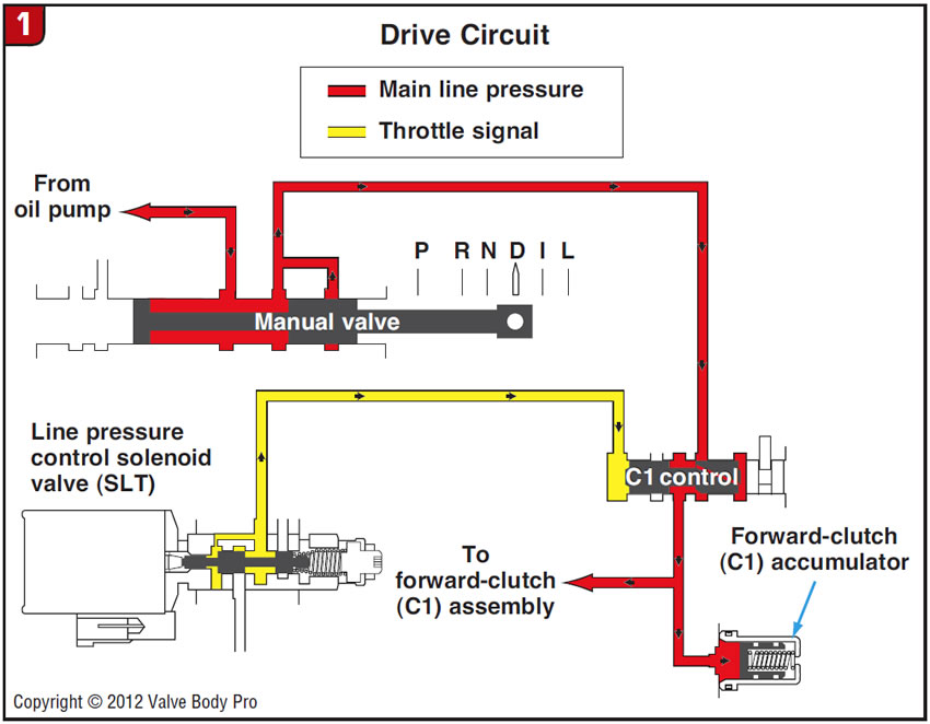
Let’s look at the Drive engagement first (Figure 1). The SLT is responsible for controlling the rate of application of the C1 forward clutch. When the manual valve is placed in the Drive position, main line pressure is directed to the center of the C1 control valve. At one end of the C1 control valve is SLT pressure and at the other end is balance oil. The SLT pressure has to gradually push the C1 control valve against balance pressure, thus controlling the rate at which main line pressure enters the circuit to the C1 forward clutch.
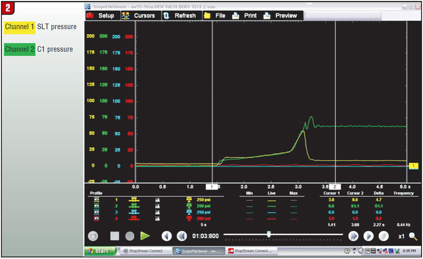
In Figure 2 we can see that the moment that the manual valve was placed in Drive, C1 pressure (green) starts to enter the C1-clutch drum, then SLT pressure (yellow) starts to increase and control the rate of apply. Then when both SLT pressure and C1 pressure are about 54 psi, SLT pressure is lowered to less than 10 psi and main line pressure is allowed to enter undisturbed the C1-clutch drum, where it settles at about 61 psi.
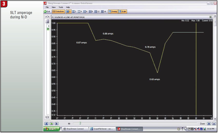
Now let’s look at how the TCM accomplishes this. You can follow the amperage activity in Figure 3. The SLT and SLS solenoids are normally open linear solenoids that decrease pressure as amperage increases. At 1 amp the SLT is adjusted to have about 5 psi, and at 0.1 amp you have about 80 psi. During the initial Drive engagement, SLT goes from 1.0 amp to 0.87, then to 0.88. This is the servo-control phase, allowing fluid to fill the clutch circuit without applying the C1 clutch. Then the amperage is gradually lowered, in increments of hundredths, to 0.78 amp. This is the torque phase that gradually applies the C1 clutch without being felt. Finally, the amperage is spiked to 0.63, which is the inertia phase, allowing full line pressure to hold the C1 clutch. SLT amperage is finally raised to 0.93 amp, where it settles, controlling main line pressure and being ready to raise it during acceleration. All this takes place in about two seconds.
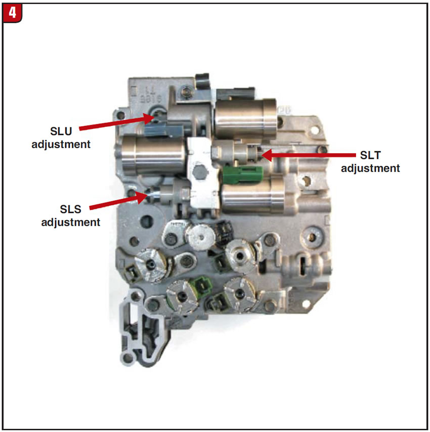
I have found the SLT to be adjusted properly – checked in Park or neutral when the transmission is hot – if set anywhere between 4 and 6 psi, but it is more stable if checked in Drive and set at 7-9 psi. If you feel a delay double bump during initial engagement into Drive, SLT pressure is probably too low. If, on the other hand, you feel a harsh engagement it is probably too high. I recommend using a pressure transducer gauge to adjust the SLT, but if you use a regular needle gauge it is better to use the 0- to 100-psi gauge, as it is more accurate at low pressure. I have found that there are 12 clicks in one complete turn of the SLT adjuster and that each click makes a difference of about 1 psi, so 1 turn equals 12 psi (Figure 4). Turning in the adjuster increases SLT pressure; turning it out decreases the SLT pressure.
Now let’s look at the initial Reverse engagement (Figure 5). When the manual valve is placed in Reverse, main line pressure is routed to the shift-pressure control valve, where it is then routed to the C2-clutch drum through the shift-pressure relay valve held in position by shift solenoid E.
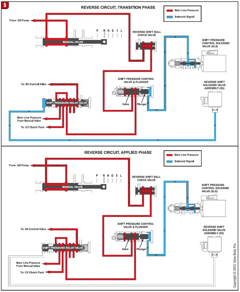
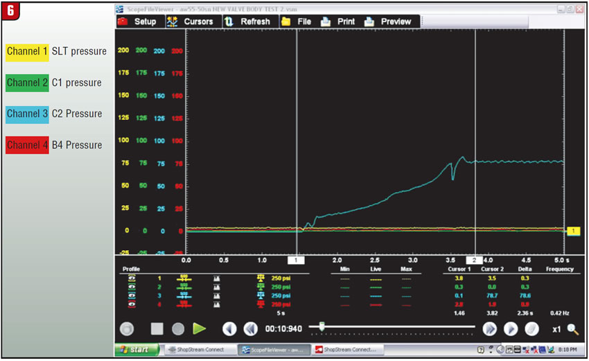
The SLS linear-solenoid pressure controls this pressure rise by gradually increasing SLS pressure present at the shift-pressure control plunger. This allows the SLS to raise the torque-phase pressure gradually from 17 psi to 75 psi (Figure 6), then shift solenoid E turns on, allowing main line pressure present at the shift-pressure relay valve to be directed to the C2-clutch drum; this is the inertia phase.
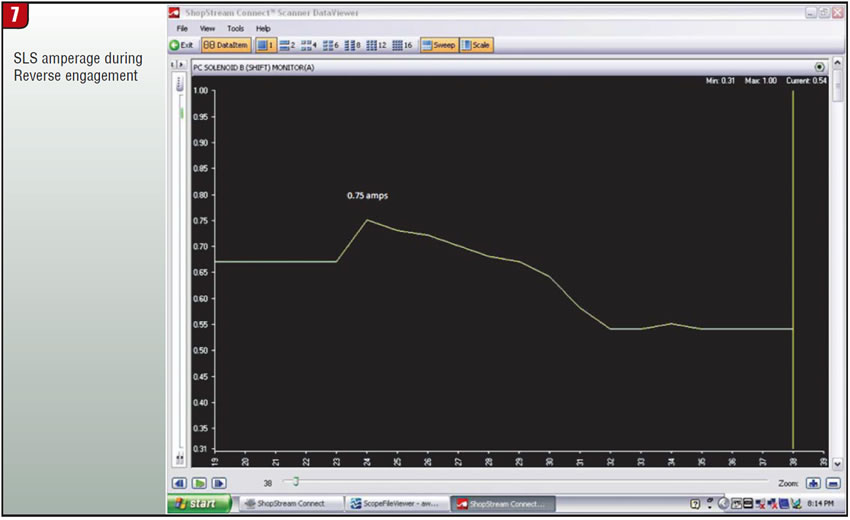
Now let’s look at how the TCM accomplished this smooth engagement (Figure 7). SLS amperage was at 0.67 in neutral. When the manual-lever position sensor noticed that the transmission was placed in Reverse, the amperage was raised to 0.75; this is the servo-control phase. Then SLS amperage is gradually lowered from 0.75 amp to 0.54; this is the torque phase. At this stage, shift solenoid E is turned on, resulting in the inertia stage, or fully applied.
In Figure 6, when you see the drop in C2 pressure at about 3.5 seconds, this is when shift solenoid E is turned on.
If you have a double-bump feel or delay in Reverse engagement and a flare on the 2-3 or 3-4 shift, SLS pressure is probably too low. If, on the other hand, you have a harsh Reverse engagement and harsh 2-3 shift, SLS is probably too high. As mentioned previously, turning in the adjuster increases SLS pressure, and turning it out decreases SLS pressure, with each click equal to 1 psi.
I hope this information helps you understand the role that SLT plays in the initial Drive engagement and the role SLS plays in the initial Reverse engagement.
Jesse Zacarias is the owner of Elec-Tran Diagnostics (www.electrandiagnostics.com) in Gilroy, Calif.


