
TASC Force Tips
- Author: Bob Warnke
Join the club
If you have encountered an AW55-50SN with an intermittent 2-3 flare and/or a harsh 3-2 downshift, you are already a member of this club. If you have not, chances are you will be joining soon. This problem can appear in your shop, dressed as a Nissan, Volvo, Saab, GM, Saturn, Renault or Opel.
By the time they arrive, they are well-seasoned units, although not necessarily what you would consider high-mileage. Although these automakers use the same transmission, there will be variations in the shafts, drums, converters, valve bodies and TCM calibration. The 2-3/3-2 shift issues are common, regardless of brand, and may be accompanied by codes P0780/785 or P0745.
Power flow during 2-3 & 3-2 shifts:
Successfully completing the 2-3 upshift requires the correctly timed application of the B-4 band and the release of the B-5 brake clutch. B-4 band application can be described as self-loading, because the rotation of the drum and servo travel are in the same direction. Clutch-plate rotation has no effect on apply or release timing in the B-5 clutch. Subsequently, 2-3 shift timing requires matching the rate of change in drum-rotation speed to the release of a clutch.
On the 3-2 downshift the B-4 band releases and B-5 clutch applies. In some situations, such as coasting or turning maneuvers, the axles are loading and driving the 4-5 drum (B-4 band surface). This variation in the torque load on the drum means there would be a variety of band-apply forces required to hold the drum. Band-release timing might be perfect at a given load but can be either too early or too late as the load fluctuates. An aggravation occurs when the timing among the TCM, solenoids and valves allows a B-4 release but a delay in B-5 apply. The unit basically has a neutral condition resulting in a 3-2 coast-down or maneuver bang.
A manual repair option, while the unit is still in the vehicle, is to alter the servo pin to arrive at 0.095 to 0.110 inch travel, or update the servo cushion spring. This may reduce the severity or frequency of the condition, but generally it is not 100% successful. Volvo suggests an updated servo and cover, explained in bulletin # 43-37, 2-25-03.
In-vehicle diagnostics:
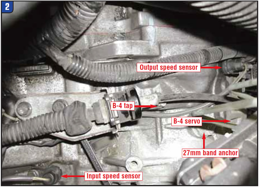
This transmission has pressure ports available for all circuits (figures 1 & 2).
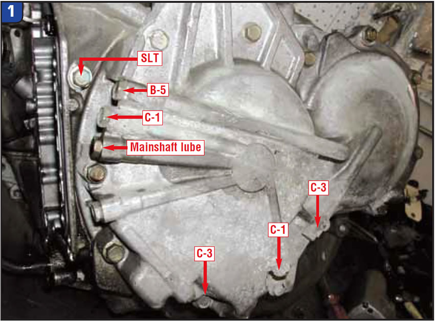
If the unit is still in the vehicle, start with a good set of gauges or, preferably, transducers at the B-4 servo port and compare it with the C-1 clutch. These pressures should be the same or not vary by more than 10 psi in third. If B-4 is lower than C-1, it is possible the servo feed-tube O-rings are leaking. If C-1 is lower, you have a problem, because C-1 is the input clutch and pressure fluctuations create delayed engagement and flare shifts.
Next step is to move from the C-1 port to the B-5 clutch port. Monitor the time it requires for the B-5 to release and B-4 to apply. Do you have a prolonged low or zero gauge reading? If so, that is a valve-body or solenoid-control problem.
Caution: Do not mistake the large 27mm nut on top of the case for a pressure port! It is the B-4 band anchor.
The last port to monitor is the SLT port. SLT is the torque-sensitive line-rise pressure. It must react to engine load as if tied to your MAF signal. Ensure that the output pressure does not hang at certain levels. If it does, it is very common for this solenoid or the valves it reacts on to be worn or contaminated.
Bench testing and visual inspection:
Sometimes visual inspection is the only option. In this unit, it is more common to find wear at the valve bores, not the anodized aluminum valves. Inspection should be performed with a clean bore, an LED inspection light and a set of reading glasses, which magnify the problem. Wear that is significant enough to create a 2-3 flare, the loss of SLT or 3-2 clunk appears as nothing more than a slightly polished half moon in the casting. The B-4 release-valve bore requires only a very slight edge next to the spring spool to create the problem.
Valve-body precautions specific to 2-3/3-2:
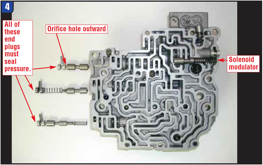
This valve body uses an extensive series circuit for 2-3 and 3-2 control. All the effective valves must be sequenced properly, which means their circuits and end plugs cannot cross-leak.
The most-overlooked bore related to our complaint is the B-4 release near the spring spool area (Figure 3a). It may appear as if you can buff out the ridge wear, but with the existence of a cross leak the valve is almost certain to hang up.
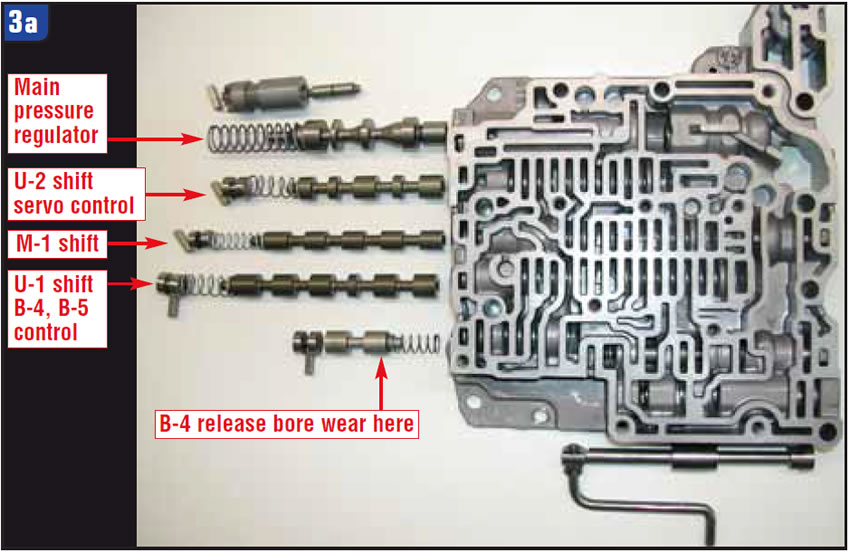
In some applications the B-5 control valve has a return spring (Figure 3b). The existence or absence of a spring corresponds to a specific separator plate and TCM calibration.
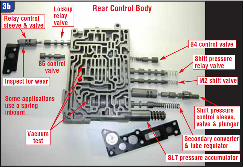
Generally, the B-5 spring is in later applications. The separator gaskets vary and must match the plate and the casting.
You can create a 2-3 issue by mismatching gaskets. The cover gaskets can be positioned to restrict the on/off-solenoid orifices. The message here is, be very cautious when exchanging valve-body components.
Line rise is critical on this unit. As you inspect these castings, you will find wear at many of the SLT linear-solenoid junctions. Last but not least, the fluid source that feeds all the linear solenoids, the solenoid modulator bore, is one that is commonly worn and always deserves careful inspection (Figure 4).
Solenoids:
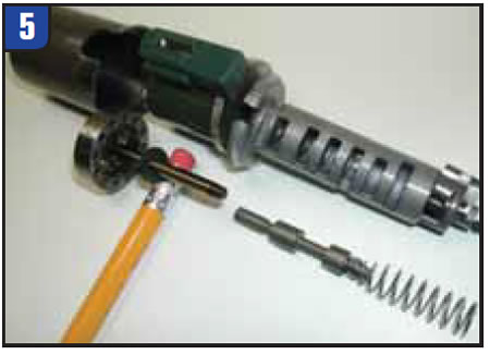
The linear solenoids (SLU, SLS and SLT) modulate the clutch pressure, and the on/off solenoids control the path the fluid takes. Problems with the linear solenoids include contamination, spring sag and wear, and they have a critical adjustment procedure. Figure 5 is an exploded view of a linear solenoid. The two solenoids we focus on for this material are the SLT and SLS. The SLS is pulsed on each shift to interrupt the clutch pressure, and the SLT ramps the clutch and line pressure to match engine load.
As mentioned earlier the solenoid modulator valve feeds all the linear solenoids. You can compare its function and related concerns to the GM actuator-feed-limit valve. Wear reduces pressure to the solenoids so they are slow to react, but wear also reduces the maximum output. The solenoid modulator can be tested at the SLT port. At maximum line, SLT should not exceed 90 psi.
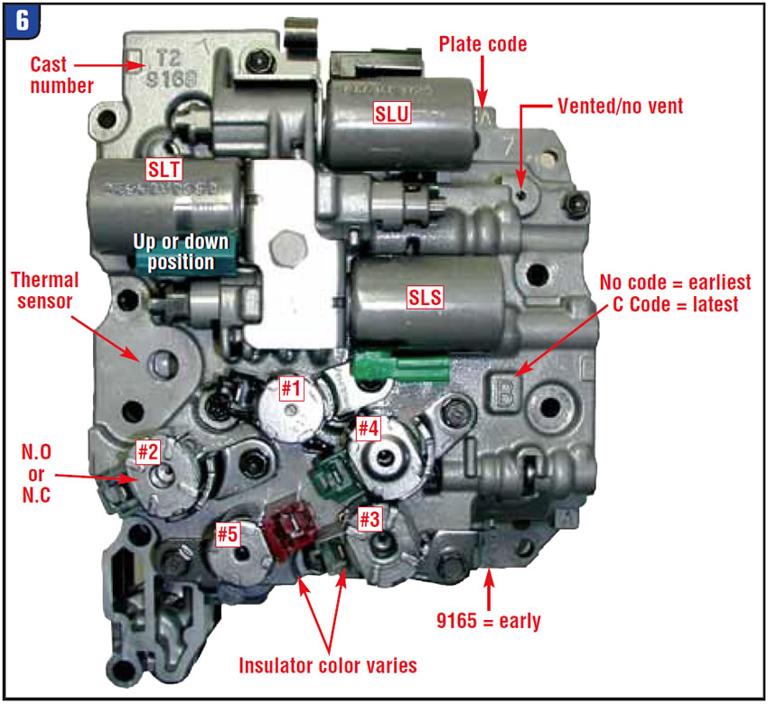
On/off shift solenoids must be able to flow more than their feed orifices supply when open. Restricted or leaking solenoids position a valve midway. To flow properly it must snap in or out quickly. The solenoids are fed from line-pressure orifices within the top cover plate. Be careful, as the #2 solenoid varies by application and can be either normally open or normally closed. It is also easy to mix the connectors between the S1 and S3 (Figure 6).
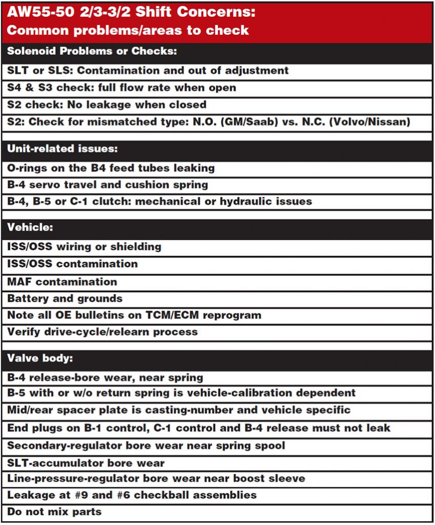
This material has been put together to help you understand both where and what to look for when searching for the cause of these common shift concerns. After reviewing this article, use the quick guide below to help you quickly locate and evaluate known trouble spots.

This material was written in collaboration with various Sonnax TASC Force members. We suggest you review the July 2008 article on adaptive relearn by Jeff Parlee of VBX and the one in February 2008. These articles, as well as other Sonnax product and diagnostic information regarding the AW55-50SN, can be found on the Sonnax Web site, www.sonnax.com.
Bob Warnke is Sonnax vice president of technical development and a member of the Sonnax TASC Force (Technical Automotive Specialties Committee), a group of recognized industry technical specialists, transmission rebuilders and Sonnax Industries Inc. technicians.


