
TASC Force Tips
- Author: Ed Lee
Before digging into this article, you should first read Wayne Colonna’s article “A Case of Mistaken Identity” that appeared in last month’s Transmission Digest. If you didn’t catch it in the March issue, please take a minute or two and read it before proceeding. What follows will make a lot more sense once you have read his article.
When filling the front-wheel-drive Jatco five-speed, it is not difficult for the technician installing the transmission to mistake the band-anchor stud for the fill plug. In fact, as Wayne explained, it’s not difficult to make this same mistake twice. When you consider that the shortest R&R time is 4.5 hours on Volkswagen, and the longest R&R time is 9.6 hours on the Freelander, it is important to figure out a way to rectify this problem without removing the transmission from the vehicle.
Don’t drive if no reverse
It is important that you identify the problem immediately. Do not road-test the vehicle to check out the forward speeds if you are having a problem with reverse. The reduction band must be anchored to the case by the anchor stud to prevent rotation. If you try to drive the vehicle without the stud in place, the band will rotate, wedging itself between the drum and case. This will prevent the drum from rotating and will burn the clutches that try to apply for a given gear. If the clutches lose their service ability, then the transmission must be removed.
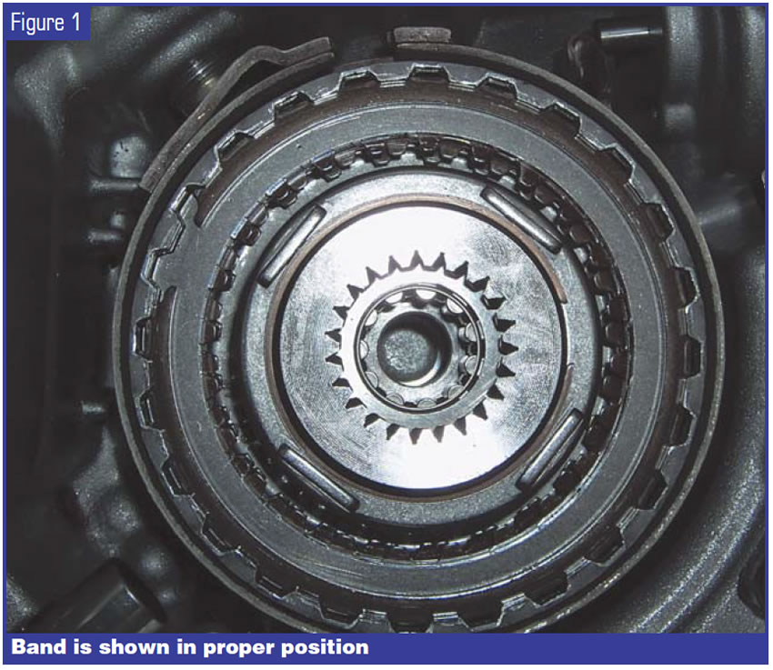
First you need to realize what is involved in the process of returning the band to its anchored position. The band looks like a shrunken-down version of the forward band in a 4T60-E. When the band is in its proper position in the case it looks as it is pictured in Figure 1. The anchor stud fits into the oval hole on one end of the band, and the servo pushes against the other end of the band for band apply. The natural spring tension of the band aids in its release of the drum as the servo releases its pressure on the band.
The band’s spring tension would make you think that re-installing the anchor stud into the band would be impossible. The first hurdle you have to overcome is removing the tension from the band. This can be accomplished by removing the cap from the servo cavity. Once the cap is removed you can see that the servo-release movement is limited by a snap ring. The servo piston and return spring are under the snap ring; the adjusting threads and the adjustment jam nut are above the snap ring.
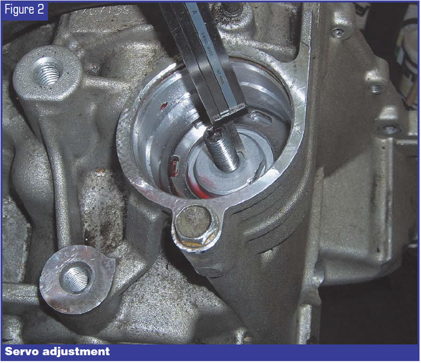
Leave the snap ring in place, loosen the jam nut and back out the servo-pin adjustment until you expose about 7⁄8 inch of threads (see Figure 2). This will allow you to rotate the band closer to the position needed to re-install the anchor stud. If you have not backed the adjustment out far enough you will still have tension on the band, and if you back the adjustment out too far the band will rotate past the servo pin.
At this point, the task still looks impossible. To make it possible, chuck the anchor stud in a lathe and drill a hole down the center of the stud. An “R” drill bit is a good choice for drilling the hole, since it is the tap drill bit for 1⁄8-inch pipe threads, and you will need to plug the hole in the stud when you are finished. Don’t forget to tap the threads into the head end of the stud before proceeding. You will not want to remove the anchor stud to tap the threads once you have it back in place.
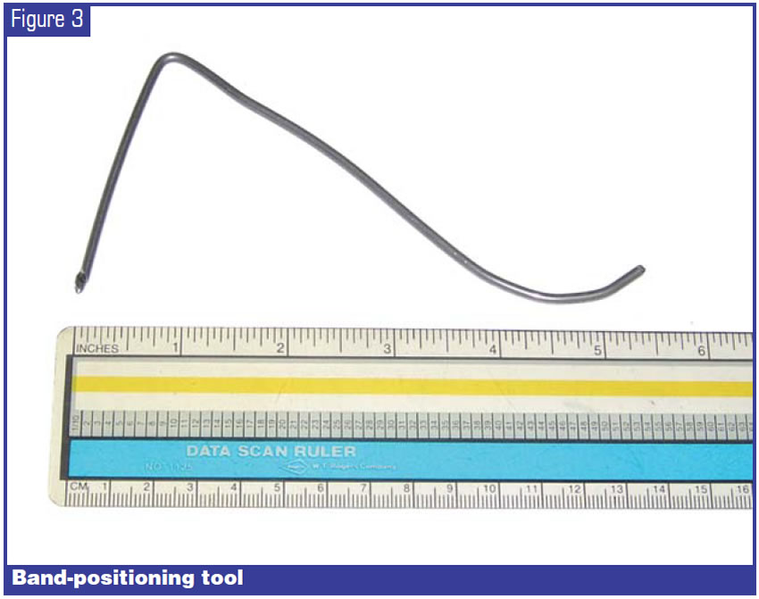
You’ll need a tool to position the band while re-installing the anchor stud. The tool shown in Figure 3 was made from 0.102-inch music wire, although any number of substitute materials can be used. The two important things are that the tool be as rigid as possible and have as much of an arch as possible and still fit down the bore of the stud. The right-angle bend of the tool will help to guide the blind end of the tool.
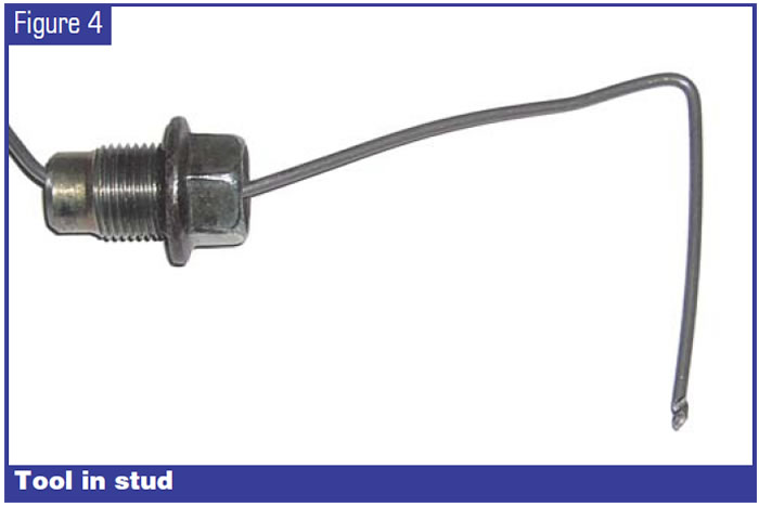
If the band is wedged between the drum and the case, tap it free. Center the band, then rotate the band until the servo end of the band is resting against the servo pin. The oval hole in the band will now be exposed through the anchor-stud hole in the case. Put the band-alignment tool through the center of the anchor stud as shown in Figure 4. The tool now can be used to position the band as the anchor stud is installed into the case. When the anchor stud is successfully installed into the case, plug the hole in the stud with a 1⁄8-inch pipe plug and adjust the clearance on the band.
In World War II, an Army engineering company had the motto, “Difficult tasks we do immediately; impossible tasks take a little longer.” When you’ve successfully replaced the band-anchor stud without removing the transmission from the vehicle, you’ll surely be able to relate to those soldiers.

Ed Lee is a Sonnax technical specialist and a member of the TASC Force (Technical Automotive Specialties Committee), a group of recognized industry technical specialists, transmission rebuilders and Sonnax Industries Inc. technicians. ©2005 Sonnax


