R&R Tech
- Subject: Amperage-based testing on a live circuit
- Unit: 4T65-E
- Vehicle Application: 1998 Oldsmobile Intrigue 3.8L
- Essential Reading: Diagnostician, R & R
- Author: Chris Adams
I think I can safely say that we have all been here before: “I ohm-checked the entire circuit and it checks OK.”
This article started as a problem found on a particular vehicle, and then it morphed into an article on – in my opinion – a better, faster, more-efficient way of checking electrical circuits on a vehicle. In this example I want to show how amperage-based testing on a live circuit can save you time and headaches versus traditional resistance testing on a dormant circuit.
The example used here is a 1998 Oldsmobile Intrigue 3.8L with a 4T65-E transaxle that has a P0753 electrical code – 1-2 shift solenoid circuit – stored in the PCM; no other DTCs are present. The code will not set until the 1-2 solenoid is commanded to turn on. Now we have all seen the diagnostic flow chart for this code. No matter which repair-service publication you use they are all basically the same: Check resistance from here to here and here to here, from there to there and from here to ground, blah blah blah; I think you know what I mean. Then we print off a wiring diagram so we know what to look at.
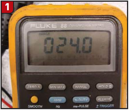
On this vehicle, when you would check resistance of the entire circuit from the PCM to the #26 10-amp trans fuse that sends power to the transmission, you would see that it checks 24 ohms (Figure 1).
After going through the entire flow chart for this code reveals absolutely no problems and you get to the end, what does the chart tell you to do? Yep, you got it: REPLACE PCM. So you scratch your head and think: “What if I spend $400-$800 on a PCM and it doesn’t fix the car? So how can I make sure I am going to fix this car right the first time?”
I will show you how to dynamically check the circuits live, with the help of a scan tool capable of bi-directional control; one of my favorite tools, a “Fuse Buddy”; a DVOM; and a handy little homemade load simulator (Figure 2).
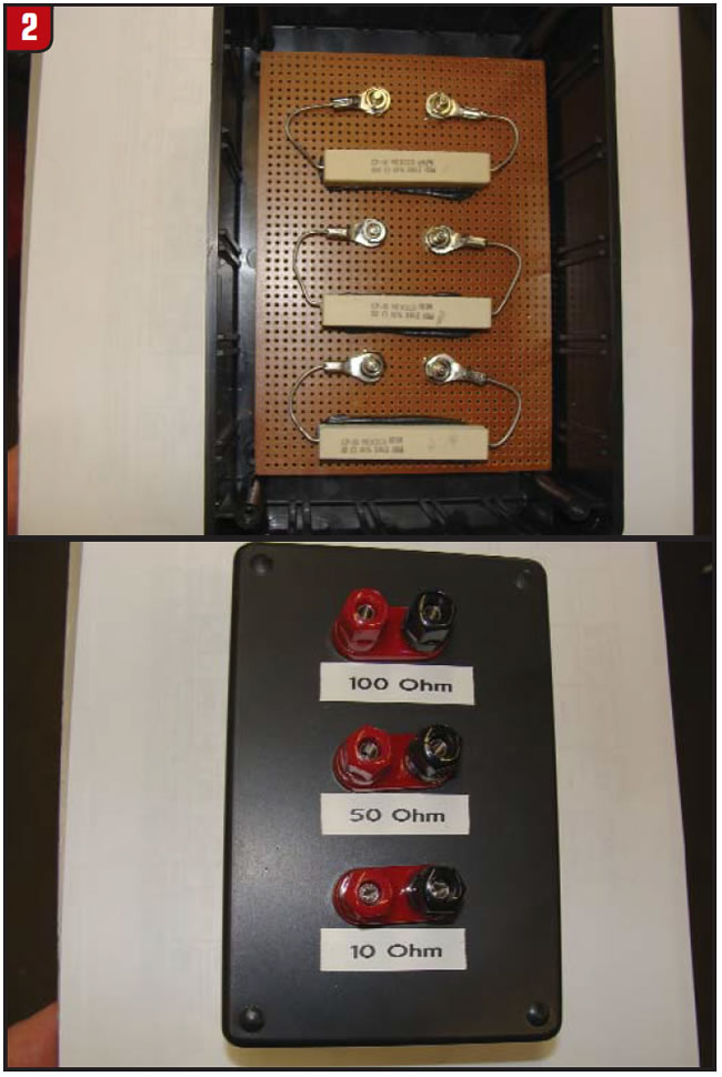
There are load simulators from tool manufacturers that are fancier than this, and some have adjustable loads; this can be made for $35 with standard parts available at Radio Shack.
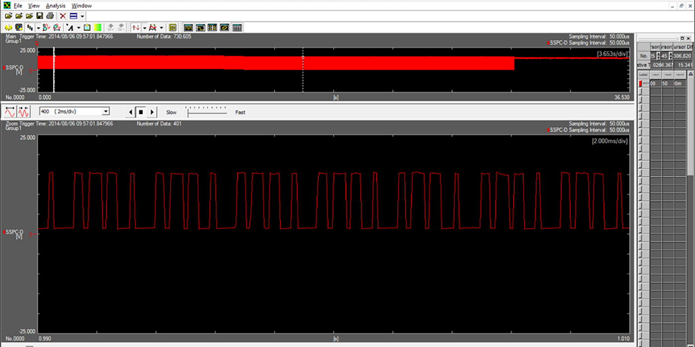
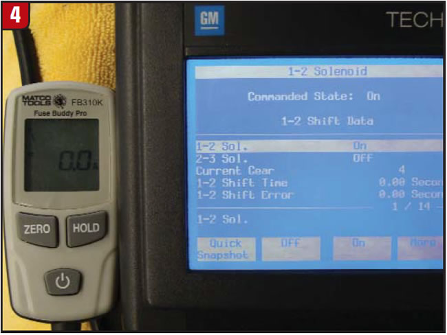
OK, let’s get started. What do we know at this point? We know that the vehicle sets a code P0753 and that the entire circuit resistance checks well within specs, so now we will connect to the circuit through the power supply (fuse) with an ammeter (Figure 3) and command the 1-2 solenoid on (Figure 4).
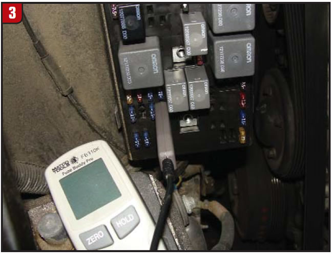
In Figure 4 you can see that the 1-2 solenoid is on but there is no current flow. Now, how can that be? Remember, “I ohm-checked the entire circuit and it checks OK.” So it must be the PCM, right? Well, at this point, it could be, but let’s make sure.
Since we started this diagnosis by using the traditional flow chart, resistance and power checks, we know that there is 12 volts at the transmission. We knew that more than likely was the case because we had only one code set. Since we’ve looked at the wiring diagram, we know that the 1-2, 2-3 and TCC PWM solenoids are powered from the same wire.
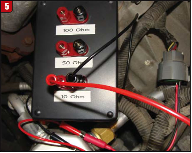
Now we hook up the load simulator to the circuit (Figure 5) and then command the solenoid on with the scan tool, and we get the same reading as in Figure 3: no current flow.
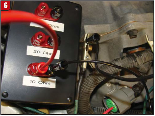
Now we are going to remove the black test lead from the connector (control side of circuit) and connect to a known-good ground (Figure 6). At this point, since the PCM controls the ground side of the circuit, all we need to do is turn the ignition on.
Now we get a reading of 1.1 amps (Figure 7). (That is the reading we would expect, since the test leads are connected to the load simulator at the 10-ohm resistor.) We now know for certain that (1) the integrity of the power-supply side of the circuit is good and (2) the problem is in the control side of the circuit between the case connector and the PCM, or in the PCM itself.
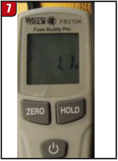
(Note: If you still had no current flow at this point, you would supply power to the load simulator’s positive lead and recheck.)

Now we are going to move the lead from the known-good ground directly to the PCM by back-probing at the PCM connector and with the scan tool command the 1-2 solenoid on (Figure 8).
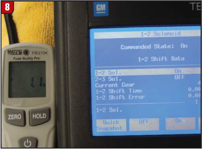
We get the same reading of 1.1 amps. We now have a foolproof diagnosis that the problem lies in the wire or connection between the case connector and the PCM, and we have also proved that the driver in the PCM is capable of handling the circuit current load.
(Note: if you had supplied separate power and ground wires to the load simulator and PCM and still had no current flow, you can prove that the PCM is unable to control the ground side of the circuit.)
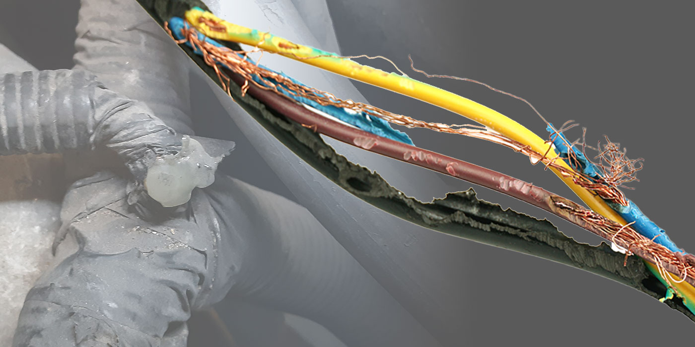
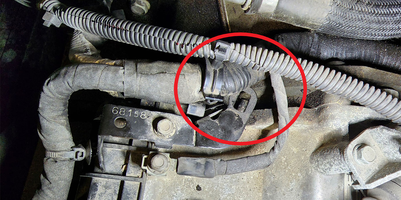
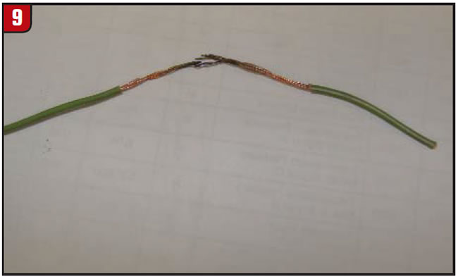
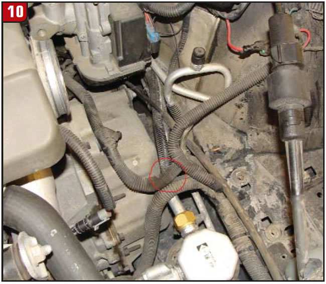
After some disassembly to gain access to the wire loom I found an improperly routed harness that was smashed under the air box, which houses the PCM. Figure 9 shows the wire that I removed from the loom, and Figure 10 shows the area where I found the problem.
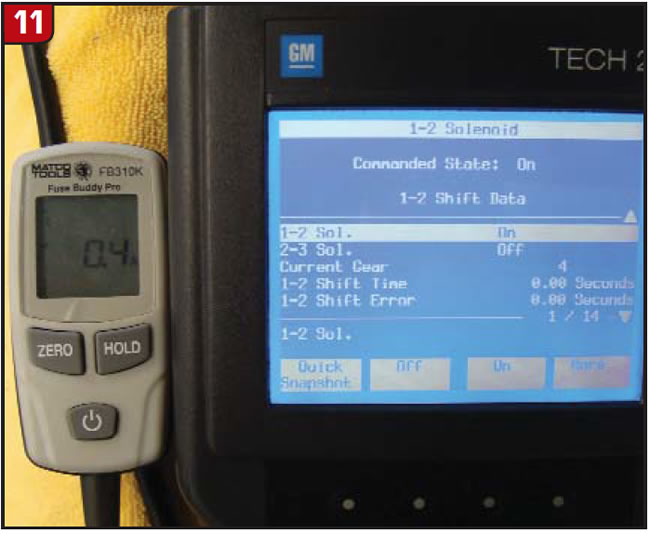
After repairing the wire, we can now test the complete circuit before we reassemble the vehicle. As you can see in Figure 11 we now have the correct current flow when the 1-2 solenoid is turned on, and the repair now is complete.
You can use this method of testing on almost any circuit on the vehicle. By using the load simulator in place of the suspected bad component and supplying separate power and ground sources you can isolate the problem and verify the repair, ensuring that you “got the job done right, the first time.”