
TASC Force Tips
- Author: Maura J. Stafford, Sonnax Industries Inc.
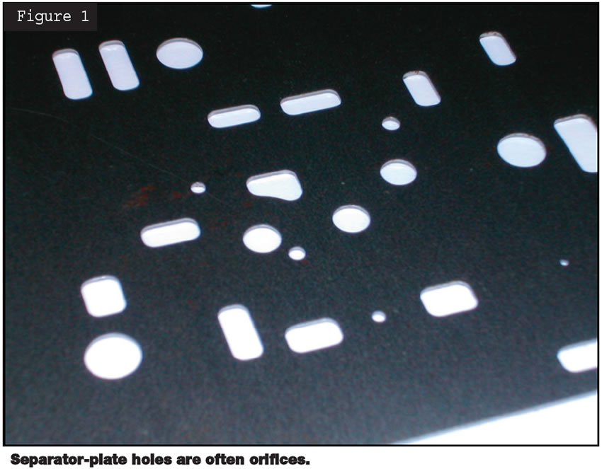
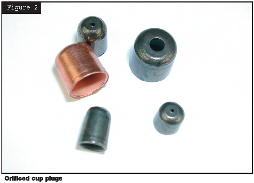
It may seem obvious initially, but when you’re talking about transmission orifices, size does matter. What may be surprising, though, is how significant a difference in vehicle performance small changes in orifice diameters can make. This becomes important when you’re considering modifications to separator-plate holes (see Figure 1) or cup-plug orifices (see Figure 2) during a rebuild.
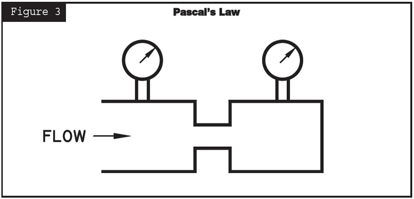
First, let’s go over the basics of orifices. Orifices are used in transmissions as a simple and inexpensive means for controlling fluid flow and pressure. When fluid encounters an orifice, flow is restricted because there is not enough room for the full flow to continue. If the path downstream from the orifice is blocked, the pressure on both sides of the orifice eventually will equalize (Pascal’s Law, Figure 3). This type of orifice restriction is used to delay pressure buildup or control flow volume. It is commonly used in balance circuits of regulating valves to reduce the busyness of the valves while maintaining the specific actuating pressure. It is also used for applying clutches gradually to provide smooth shifts.
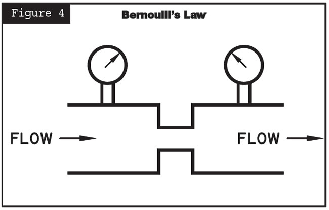
If the path downstream from the orifice is not blocked, a pressure differential is created at the orifice (Bernoulli’s Law, Figure 4). This is a simple method of reducing hydraulic pressure. For example, adjusting the position of a valve controls the percentage of port opening. This opening actually acts as a variable orifice size, which then alters the pressure differential.
So altering the size of an orifice will affect the pressure differential and/or timing of the devices. Depending upon the application, this could alter vehicle performance significantly. For instance, excessively enlarging an orifice in an accumulator or clutch circuit will affect the apply and release timing, which could create a harsh shift, a flare or a bind-up condition.
Enlarging the orifice of a regulating valve could result in valve buzz or hammer, or overly responsive valves, leading to pressure fluctuations and premature wear. On the other hand, orifices that are too small will affect operation adversely in colder temperatures when the ATF is more viscous. This is not to say that orifices should not be adjusted, only that some care and thought should go into it before you reach for the 1⁄8-inch drill bit.
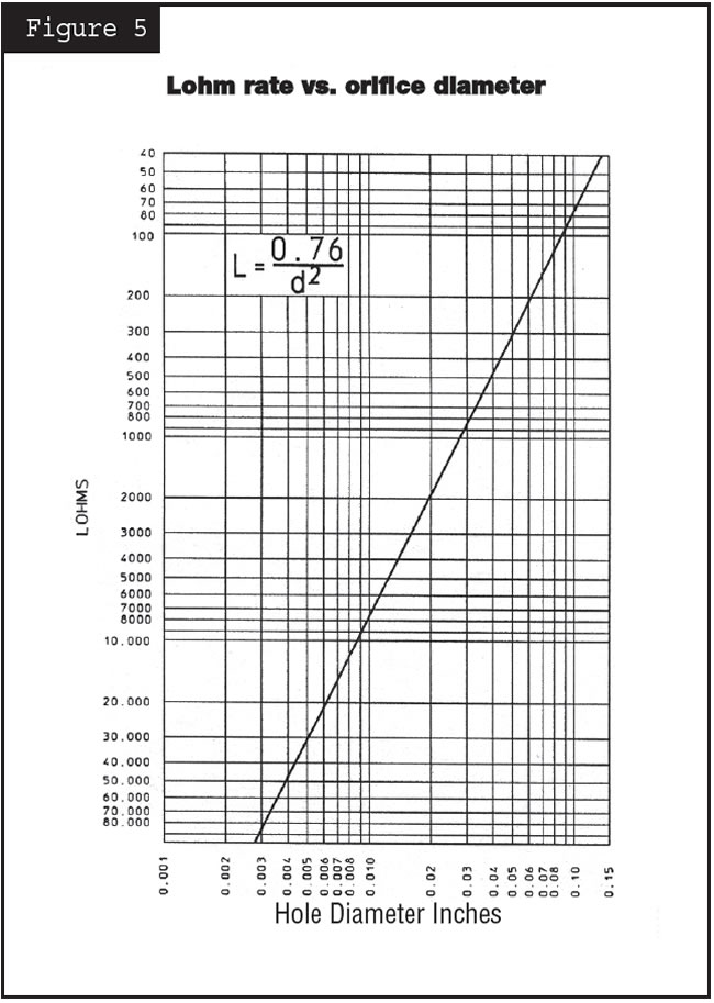
In determining fluid flow rates through orifices, typically things like temperature, specific gravity and fluid viscosity need to be considered. However, if all of these variables remain the same, the “Lohm” can be used. This is a simplified system of determining equal flow rates with different orifice sizes. The smaller the Lohm rate, the more flow allowed (Figure 5). To determine an orifice’s Lohm rate, use the following equation:
- Lohm = 0.76 ÷ D2 (D = diameter)
As examples, let’s determine the Lohm rates for orifices o 0.030-inch and 0.060-inch diameters.
- 0.030 inch – Lohm = 0.76 ÷ 0.0302 = 844
- 0.060 inch – Lohm = 0.76 ÷ 0.0602 = 211
This points out a common misconception: that if you double the diameter of the orifice you are also doubling the flow rate. This is not true! In actuality, doubling the diameter will create four times the flow rate. This also means that two parallel orifices of 0.030 inch diameter do not equal the same flow rate as one orifice at 0.060 inch. It actually would take four 0.030-inch parallel orifices to equal one at 0.060 inch.
Here is another example of what happens when you’re enlarging an orifice:
- Diameter of original orifice = 0.040 in. (0.00126 sq. in.)
- Enlarged orifice = 0.050 in. (0.00196 sq. in.)
- Increased diameter by 25%
- Increased area by 56%
- Increased flow rate by 56%
This shows that while the actual orifice diameter was increased only slightly, the affect on area, and thereby flow rate, was much greater. This means that small changes in orifice diameter will significantly affect the timing or relative pressure differential. Keep this in mind the next time you are making any changes to separator-plate holes or cup-plug-orifice diameters. Make gradual enlargements and test to see what impacts these have on vehicle performance, and then go larger if necessary.


