TASC Force Tips
- Author: Brian Wing
- Subject Matter: Opening orifices or not
- Issue: Details of drilling
A small change in diameter can make a big change in area
Modifying orifice size in valve body separator plates has been practiced as long as automatic transmissions have been in existence. From performance upgrades to attempting to fix problems caused by valve-body wear, opening up orifices can provide positive effects – but can just as easily cause unforeseen problems. To avoid unwanted results, it is necessary to know when to drill, what size to drill to and when not to drill.
Increasing clutch feed orifice size is a proven way to improve clutch engagement time and firm up shift feel. This helps with otherwise lazy-shifting transmissions, hardworking commercial applications or units modified for performance use. But all too often when a feed orifice is enlarged, the hole is drilled too big and the change in shift feel is far greater than intended. This often results in harsh shifts, which many customers do not like and view as a nuisance. When other orifices are enlarged in an attempt to overcome leaks or other problems, it can cause a host of issues such as pressure fluctuation, converter drain back, noise, pump damage, etc.
You can navigate the minefield successfully by understanding why some orifice modifications have better alternatives and how orifices are commonly drilled too large as a result of incorrect calculation. When considering modifications, avoiding these pitfalls will help you bring a smile to your customer’s face.

In a nutshell
Separator-plate orifices are precisely sized holes that restrict fluid flow, reducing the speed of the oil in a given circuit. They work in tandem with valves and checkballs for timing purposes and to prevent valve fluctuation. For example:
• On the feed side of clutch and band circuits, a restriction serves to control the gear application to prevent harshness.
• On the balance end of pressure regulating valves, a restrictive orifice is needed to dampen pressure pulses from the pump that would otherwise cause the valve to move erratically and buzz audibly.
Common mods & side effects
Balance
As regulator valve bores wear over time, the increased leakage past the balance end of the valve is too much for the orifice to flow, and the valve only strokes partially – or not at all. This positions the valve in a high or max pressure position. Opening up the orifice to flood the balance end in an attempt to overcome this leakage is something that has been widely performed. From AFL and solenoid modulators to TCC, mainline and secondary pressure regulators, builders have had mixed results with this practice.
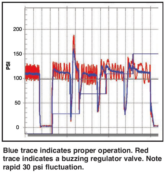
The reason for such inconsistent results is that enlarging the balance orifice makes a BIGGER leak in an effort to mitigate a problem caused BY leaking. The extra volume might overcome the effect of the balance leak and get the valve operating closer to its proper range (for a while), but we are simply sending more oil volume into the leaking area to be exhausted. This causes the pump to work harder, which can lead to wear or damage. In addition, now that some of the precise control variables designed by the OE engineers have been altered – the valve/bore tolerance from wear, coupled with the balance feed change – there can be unexpected problems with proper valve return, valve vibration/buzz and/or unstable pressure (Figure 1). Multiply that across other bores in a tired valve body and you can see why it doesn’t always seem to work, or why it seldom seems to produce fully repeatable results.
Line to lube
On units with lube issues, line-to-lube modifications of one sort or another are necessary. But drilling too large or enlarging the plate orifice when a valve body modification has already been made can allow converter drain back.
TCC
TCC exhaust orifices control how fast the converter releases; it is a common practice to enlarge them so that TCC apply is quicker due to diminished resistance to flow of the release oil. But the converter exhausting too fast can cause harsh lockup precisely because of that diminished resistance. Similarly, drilling to bypass the converter clutch backpressure valve on Ford 5R55W/S/N units can cause harsh lockup because resistance to exhaust of release oil has been reduced.
Actuator feed limit
Another widespread practice is to enlarge the solenoid feeds in GM units as a Band-Aid for low AFL pressure. AFL pressure is typically equal to line pressure until approximately 110-120 psi. Opening these feeds may result in a small drop in line pressure and can cause the solenoids to flood and partially close.
Performance
Chrysler 46/47/48RE units often bind up when over-enlarged direct-feed holes are used in tandem with a performance servo.
With any of these modifications, it is possible to induce temperature-related problems such as normal feeling operation when cold, but adverse operation as the unit comes up to temperature.
As shown by these examples, there are factors involved that make the effectiveness of enlarging orifices to repair problems a hit-or-miss proposition. For most issues, a more effective and repeatable repair is to recondition the bore and install an oversized valve. This seals off leaks to restore normal operation; it does not create new leaks to Band-Aid others. Modifying valve control generally results in shift quality that will not meet customer expectations; do it right and reserve your drilling for performance mods.
Drilling orifices the smart way
When enlarging orifices, it is very common to drill too large because diameter often gets confused with area. A small change in diameter can make a big change in the area of the hole the oil flows through. For instance, it is easy to think that enlarging a 0.070″ clutch feed orifice to 0.100″ will provide good results. That is approximately a 43% increase in diameter, but a 104% increase in area! Drilling that large will often result in timing problems, harsh shifts, rattled teeth and possibly broken components.
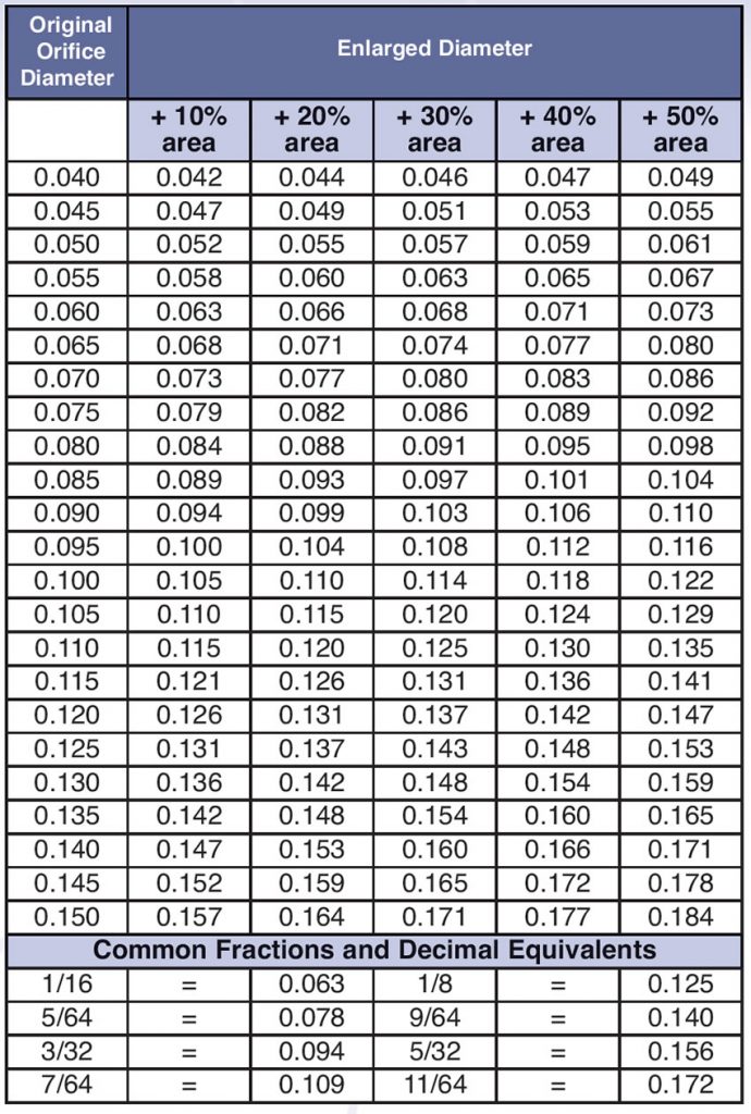
If you wish to enlarge clutch feed orifices, the following guidelines will help you determine what drill-bit size corresponds with a specific percentage increase in orifice area so you are less likely to cause problems when making common performance modifications. When tuning a transmission, experience has shown that a 20% increase in area yields a subtle yet noticeable change in shift feel without causing harsh shifts that generate customer complaints. Since the flow rate increases proportionally to the area increase in a clutch apply circuit, the clutch will also apply 20% sooner. We could analyze the mathematical formulas involved, but I’d rather just cop a cheat sheet (Figure 2). Use this chart to determine drill diameter for any increase in orifice area that you think best suits the vehicle you are working on.
Let them sing your praises
As you can see, some mods are better left unperformed when a proven, targeted repair exists. While the over-enlargement of orifices continues to be a common error for some, you now have the key to avoid going too large and causing adverse effects. Knowing when and how much to modify orifices will give you a higher success rate that your customers will absolutely love you for.