Retrofitting the GM 12-Inch 350/400 Non-Lockup Converter - Transmission Digest

Retrofitting the GM 12-Inch 350/400 Non-Lockup Converter

The GM 12-inch 350/400 non-lockup converter is still very popular with torque-converter rebuilders. The converters are needed for many vehicles from that era that are being restored, and even more are used in the construction of street rods. The high demand and limited availability for cores have been an issue with some rebuilders. The lack of cores is easy to understand when you consider it has been more than three decades since the last GM 12-inch non-lockup converter was manufactured.

Retrofitting the GM 12-Inch 350/400 Non-Lockup Converter

Torque Converter Tech Tips

Subject: Replacing the GM 12-inch non-lockup converter with a 298mm converter
Unit: THM 350/400
Essential Reading: Rebuilder
Author: Ed Lee

Torque Converter Tech Tips

  • Subject: Replacing the GM 12-inch non-lockup converter with a 298mm converter
  • Unit: THM 350/400
  • Essential Reading: Rebuilder
  • Author: Ed Lee

The GM 12-inch 350/400 non-lockup converter is still very popular with torque-converter rebuilders. The converters are needed for many vehicles from that era that are being restored, and even more are used in the construction of street rods. The high demand and limited availability for cores have been an issue with some rebuilders. The lack of cores is easy to understand when you consider it has been more than three decades since the last GM 12-inch non-lockup converter was manufactured.

Some innovative shops have solved the core issue by retrofitting a common late-model 12-inch lockup converter: the 298mm used in the late-model GM overdrive transmissions (e.g., 2004R, 700R4 and 4L60-E). This converter can be easily adapted to the early-model, non-lockup transmissions with a few modifications. It already has a couple of common characteristics with earlier units: a 1.703-inch-diameter pilot, three-lug-bolt circle and the same input and stator spline counts.

Adjusting the overall height and eliminating the lockup clutch are the only two challenging issues in retrofitting late-model 12-inch lockup converters with the 298mm. With the help of some parts already available through the aftermarket and a small amount of machine work, these issues can be overcome.

A clutch eliminator for the 298mm converter is available but is too tall (1.500 inches) in its original form (Figure 1).

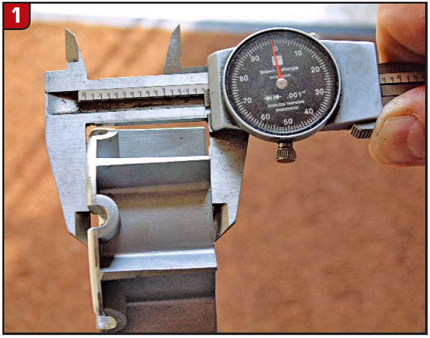
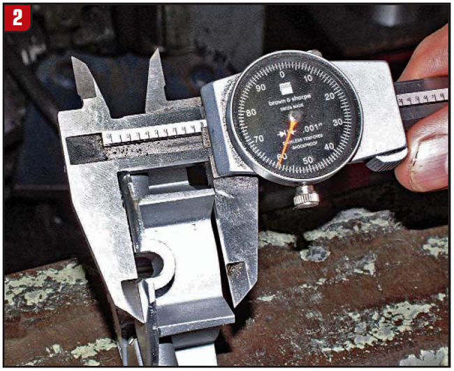
Machining the clutch eliminator to a length of 0.940 inch will allow it to be used in the retrofit converter (Figure 2).

Adjusting for the differences in the overall height of the converters is a two-part process.

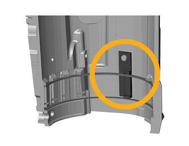
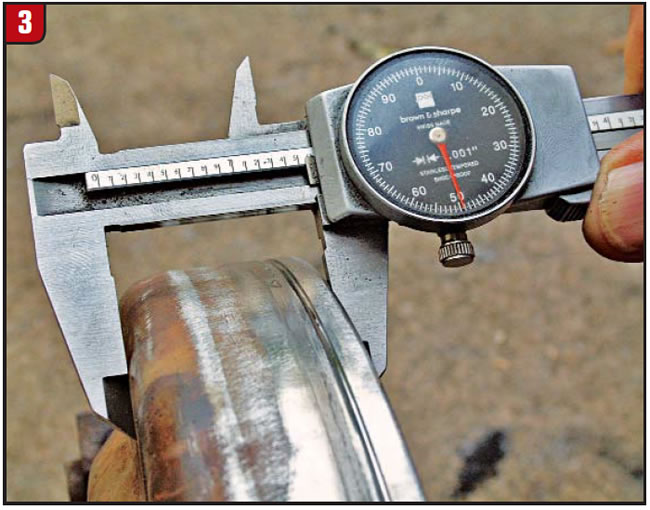
First, the lip of the 298mm cover where the impeller overlaps the cover needs to be shortened to make up for the space created when the clutch was removed. The OE cover measures a little more than 1.500 inches from the front of the cover to the top of the lip (Figure 3).

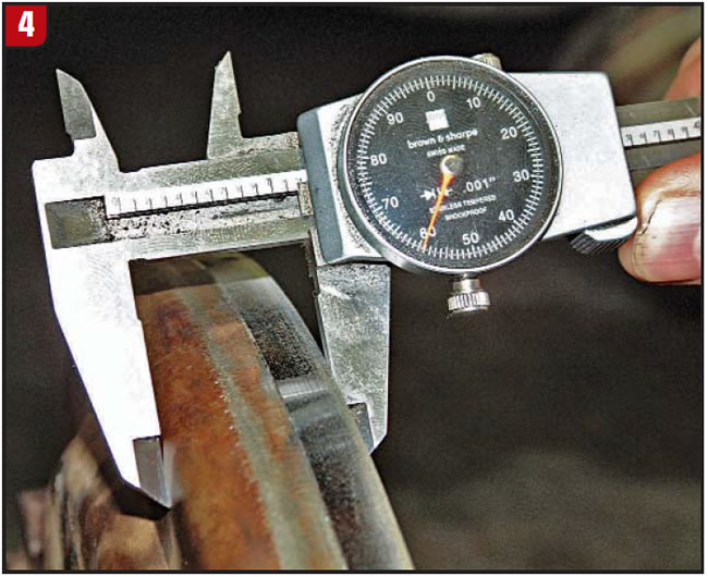
This measurement needs to be about 1.160 inches for the retrofit (Figure 4).

Before you take the cover from the lathe, you may want to remove a small amount of metal from the outside diameter of the cover to ensure that the impeller overlaps the cover without interference. This also would be a good time to polish the thrust surface of the cover where the clutch eliminator will ride. A 20 or finer RA on the thrust surface will increase the life of the clutch eliminator.

The second part of adjusting the overall height is the replacement of the impeller hub. The non-lockup converters are about 0.225 inch taller than the lockup converters in their stock form, and this dimension increases when the clutch is eliminated, so a taller hub is needed. Fortunately, there is a stock replacement hub that fits the need: the butt-style replacement hub used on the 180/Holden converters.

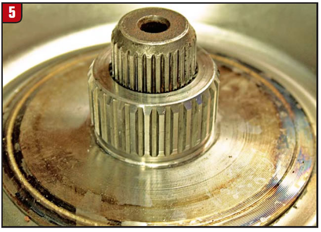
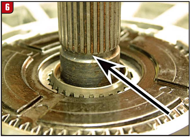
When you are checking the converter stab depth, the pump-drive slots in the impeller hub bottom on the lugs of the pump gear. If you have a keen eye for detail, you will notice in this retrofit setup that the input splines in the turbine hub bottom on the input shaft slightly before this happens (figures 5 & 6). This will make a difference when you’re checking the stab depth of the converter, but the difference is very minimal and no corrective action is necessary.

Special thanks to Frank Brunner for providing the information for this article.

Ed Lee is a Sonnax technical specialist who writes on issues of interest to torque-converter rebuilders. Sonnax supports the Torque Converter Rebuilders Association. Learn more about the group at www.tcraonline.com.

You May Also Like

Sherlock Holmes Approach to an AB60 No-Move Situation

The effectiveness in diagnosing automatic transmission malfunctions is an art form. Although there are similarities among the wide varieties of transmissions on the road, each transmission has its own peculiarities. Aside from having mechanical, hydraulic, and electrical hardware systems to contend with, software/programming issues and various vehicle platforms make diagnostics much more difficult.  Using scopes provides

ab60

The effectiveness in diagnosing automatic transmission malfunctions is an art form. Although there are similarities among the wide varieties of transmissions on the road, each transmission has its own peculiarities. Aside from having mechanical, hydraulic, and electrical hardware systems to contend with, software/programming issues and various vehicle platforms make diagnostics much more difficult. 

GM 6T40 Pump Identification Guide

The 6T40 was introduced in 2008 for General Motors front-wheel-drive cars in the Chevrolet Malibu and has gone through several changes throughout its three generations, specifically in the pump area. The 6T40 is closely related to the more lightweight 6T30 and the heavier duty 6T45 and 6T50. Generation one started phasing out during the 2012

Seeing the Forest AND the Trees

They say that the proverbial phrase “I couldn’t see the forest for the trees” means that a person or organization cannot see the big picture because it focuses too much on the details. Related Articles – 4L60E Harsh 1-2 Shift – TASC Force Tips: Diagnosing 8L45 & 8L90 Shift Complaints – TASC Force Tips: Hydraulics

The Manifold Pipeway

The Honda six-speed transmission has been on the bench of many specialty shops for one reason or another (figure 1). But, for those of you who have yet to lay your hands on one, mounted on the upper side of the unit is one of the largest, if not the largest solenoid and pressure switch

8L90 Vacuum Testing

Below are the diagrams for vacuum testing GM 8L90 transmissions. Note: OE valves are shown in rest position and should be tested in rest position unless otherwise indicated. Test locations are pointed to with an arrow. Springs are not shown for visual clarity. A low vacuum reading indicates wear. For specific vacuum test information, refer

Other Posts

GM 400, 4L80-E Case Saver Retainers

Protect case lugs from blowout with the only intermediate clutch retaining ring case saver that allows the intermediate band to be retained. Only the Sonnax case saver retainers support the intermediate clutch retaining ring, yet are thin enough to allow the intermediate band to be installed, allowing case lug protection in all applications. Related Articles

Heavy-Duty TH350/350C Intermediate Outer Race

Tri Component has announced the availability of a heavy-duty TH350/350C intermediate outer race (p/n 35723HD).  Related Articles – PRT launches 30 new complete strut assemblies – Force Control Industries releases transmission fluid for oil shear clutch and brake applications  – TransGo introduces 62TE high pressure kit for vans Classic, upgraded, street units require break-resistance and

Critical Wear Areas & Vacuum Test Locations for FORD 6R80/6R100

Note: OE valves are shown in rest position and should be tested in rest position unless otherwise indicated. Test locations are noted with an arrow. Springs are not shown for visual clarity. Low vacuum reading indicates wear. For specific vacuum test information, visit www.sonnax.com. Related Articles – Hydraulics Fundamentals: Shift & Relay Valves – Another

Hydraulics Fundamentals: Shift & Relay Valves

Shift valves and relay valves share a lot of the same duties. This article is one of a series by Sonnax exploring how valves and hydraulic circuits work and what results when they quit functioning correctly.