Torque Converter Tech Tips
- Author: Ed Lee
Sometimes misunderstood, and often overlooked, but very important!
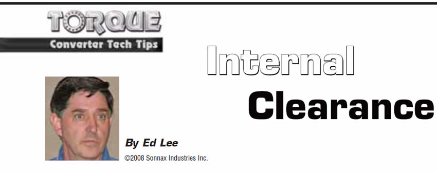
“Internal clearance” is the space between the impeller and the turbine in an assembled torque converter (Figure 1).
Hydraulically, it is the distance that the oil travels from where it exits the vanes of the impeller to where it enters the vanes of the turbine. Some rebuilders use the term “internal clearance” incorrectly. They use it to refer to the clearance between the internally stacked components of the converter. The correct term for the clearance between the stacked components is “end play.”
In a perfect world, the converter would operate at its maximum efficiency when the impeller and turbine are as close as possible, without touching. In the real world, where nothing is perfectly straight or true, some extra clearance is necessary to prevent contact between the moving parts. This extra clearance also builds in some planned inefficiency, which allows the transmission to remain in gear without stalling the engine when the vehicle is stopped. Most converters of 10- to 12-inch diameter will operate efficiently with about 0.080-0.100 inch of internal clearance. Larger converters need a little more clearance to keep the parts from touching.
Minimizing the internal clearance of a torque converter has been an effective method of lowering the stall and increasing the efficiency on converters coupled to diesel and long-stroke gas power plants. This method has been used on the Cummins diesel converters for many years.
Increasing the internal clearance to more than the OE specification will have the opposite effect. It will raise the stall and decrease the efficiency of the converter. Increasing internal clearance is the least-desirable method of increasing stall. The July 2007 Transmission Digest article Myth Busters Part 3 illustrated how small changes in stall and large changes in generated heat were caused by increasing the internal clearance in the Chrysler 518 converter in a test vehicle from 0.080 inch to 0.160 inch. The increase in internal clearance was the only change made to the vehicle, and the transmission overheated during the 21/2-minute dyno test. The greater the gap between the impeller and turbine, the greater the oil sheer, and the more heat is generated.
Modifying the impeller-blade angle or the stator is a much more-efficient method of raising the stall. Raising stall is important on a converter coupled to an engine that has had its performance enhanced by adding a modified camshaft or bumping up its compression.
There are some very obvious and some not-so-obvious by-products of having too much internal clearance.

One very obvious example
A racer was converting an ex-Pro Stock car into a Super Pro car. He was using a 540-cubic-inch big-block Ford engine with a Powerglide transmission and an 8-inch converter. The transmission was equipped with three temperature probes connected to a digital readout. One probe was in the pan, one was in the cooler line where the oil exited the transmission and the other was in the return cooler line.
The temperature probe where the oil exits the transmission is the first place the oil goes when it leaves the converter. At the starting line, this probe was already reading 190°F. By the end of the quarter mile, the temperature was reading 308°F. The racer did not need to see the temperature readings to know that he had a problem, because the paint on the converter already looked burnt by the end of the first run. By the third run, the temperatures were reading as high as 350°F and the converter was starting to fail.
The converter was returned to the shop where it was purchased, and the owner of the shop insisted that the converter was built properly and that the racer must have abused it. Over the next several weeks, the racer changed the cooler and even installed a completely different transmission but always got the same results. The transmission would run hot and the converter would last only three or four runs. The racer eventually replaced the converter and the problem went away.
Comparing the two converters showed that the only significant difference was the internal clearance. The converter that worked successfully had an internal clearance between 0.090 and 0.100 inch; the problem converter’s internal clearance exceeded 0.160 inch.
The difference in performance between the converters was dramatic. The quarter-mile elapsed time went from 8.58 to 8.40 seconds with the new converter. The 60-foot times went from 1.234 to 1.185 seconds, and the speed went from 159 to 161.40 mph. The finish-line temperature on the new converter was about 100-120° cooler than on the old converter. However, the biggest difference was that the racer was making 125 runs between cleanouts on the converter. The new converter never failed and looked so good at the time of the cleanouts that the racer got as many as 215 runs on the converter at one point.
A not-so-obvious example
A torque-converter rebuilder started to notice a higher-than-normal comeback rate on one of his Ford converters. The converters were coming back wiped out, and the Bakelite stator caps were coming out looking like small black marbles. The fluid smelled like 90-weight gear lube and the paint on the converters was burnt, so he knew that the converters were overheating. At first he blamed the customers, but too many were having the same problem. At one point a converter came back with the paint burnt, but the converter had not self-destructed. When the shop cut the converter open, the only thing they found out of the ordinary was small blisters on the side of the stator cap.
The shop owner reasoned that the stator caps were not standing up to the heat and were causing the converters to fail. The only flaw in his theory was that his friend (also a torque-converter rebuilder) was using the same stator caps and was not having any problems. He asked his friend to check his rebuild procedure, to make certain that he was not doing anything wrong. The friend found that the converter had too much internal clearance and explained that the excessive internal clearance was probably causing the converters to overheat.
At first the rebuilder thought that his friend was talking about the converter’s end play. When the friend explained what he meant by “internal clearance,” the rebuilder said that in his 30-plus years of rebuilding torque converters he had never checked the internal clearance and did not believe that it could cause the problem. He reluctantly agreed to check and adjust his converters’ internal clearance for a short time. Since then his comeback rate on the Ford converters has returned to normal, and a couple of other problems that had not been recognized also went away. Checking and adjusting internal clearance has become an important part of his converter-rebuilding procedure.
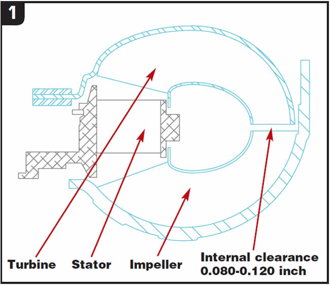
FYI
The stator cap in Figure 2 was in a low-mileage rebuilt GM converter that was returned to a builder because of a transmission-related problem. The blistering on the side of the stator cap was the result of 0.245 inch of internal clearance. This converter would have failed prematurely because of the incorrect internal clearance.
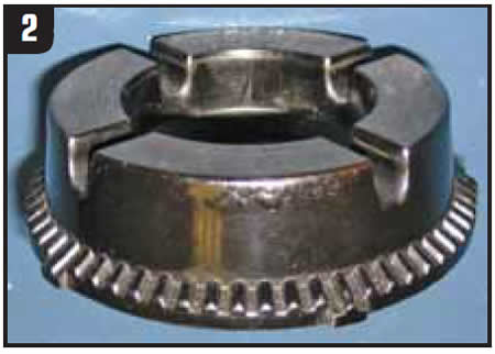
Checking internal clearance
Put the impeller on a flat surface and place the turbine (with turbine hub) right on top of the impeller so the veins are in contact (Figure 3). In that position, there is no clearance between the impeller and turbine. Measure from the top of the turbine hub down to the flat surface and record your measurement.
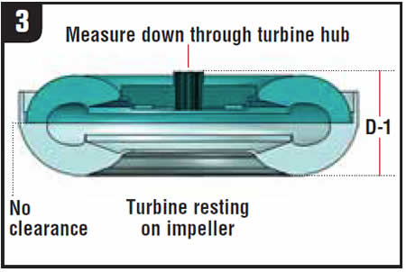
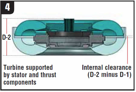
Now, take the turbine out of the impeller and place the stator in the impeller, followed by the turbine (Figure 4). The impeller and turbine are now separated by the stator and thrust washer. Once more, measure from the top of the turbine hub down to the flat surface. The difference between the two measurements is the internal clearance.
Ed Lee is a Sonnax Technical Specialist who writes on issues of interest to torque-converter rebuilders. Sonnax supports the Torque Converter Rebuilders Association. Learn more about the group at www.tcraonline.com.


