Body of Evidence
- Subject: Rebuilding linear solenoids
- Units: AW55-50, 09G, TF80, TF81
- Essential Reading: Rebuilder, Diagnostician
- Author: Jeff Parlee
The linear solenoids on the Aisin valve bodies control line pressure, shift pressure, shift/engagement feel and lockup control. A linear solenoid that is sticking can cause all sorts of problems depending on the solenoid and the transmission type. The linear solenoids need to be rebuilt as much as the valve bodies do on these transmissions. The pintles stick and the outer shell (can or shell) can become distorted or loose.
What causes the linear solenoid pintle to stick:
- The coil inside the solenoid becomes a magnet when energized and attracts metal to the inside of the solenoid. This metal, even though very fine, can become imbedded into the surface of the bushings that support the pintle. The pintle needs to move freely back and forth in the bushings at all operating temperatures. As the transmission heats up, the shaft of the pintle expands, as does the metal in the bushings, and that is usually when the pintle in the solenoid starts to stick.
- A second cause of pintle sticking after rebuilding the solenoids is that the bushings were not installed in alignment with each other. If the bushings were installed one at a time, they are probably not aligned with each other. As the solenoid heats up and the bushing and pintle expand, the misaligned bushings are more likely to cause the pintle to bind in the bushings. Using a bushing-installation tool will install both bushings at the same time, perfectly aligned with each other.
Pressure fluctuations due to the can/shell:
- Using the tool to un-crimp the shell from the aluminum snout can cause the shell to become distorted. There is a reshaping tool, but of the tools that I have tried my experience has been that the reshaping tool works only 50% of the time. Any distortion in the shell can cause the pressure to fluctuate as much as 20 psi. Using a new shell is the best way to go.
- Pressure fluctuation or change can happen because the crimp between the shell and the aluminum snout is not tight enough, allowing the shell to move.
Before we get started:
- Are any linear-solenoid electrical codes present? If so, be sure that you have found the cause of the code, as some linear solenoids will develop an open circuit when hot and test normal when cold.
- Are the electrical connectors on the linear solenoids in good condition?
- Check the linear-solenoid resistance; it should be 5.0-5.6 ohms at room temperature (68-70°F).
- You will need a tool to un-crimp and re-crimp the solenoid shell.
- You will need a bushing-removal and installation tool.
It is very important that you have rebuildable linear solenoids and that you have the tools needed to obtain the best results.

Disassembling the solenoid:
- Familiarize yourself with the instructions for your particular tool. Most tools have a base that should be installed in a vise or bolted to the bench. Put the linear solenoid into the base, put the un-crimping tool over the solenoid snout, press down and turn in the direction your instructions tell you to.
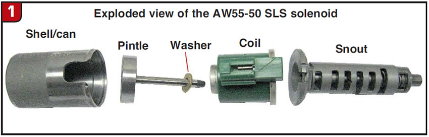
- Once the crimp is undone the snout can be removed from the shell. Next remove the coil, pintle and washer (Figure 1).
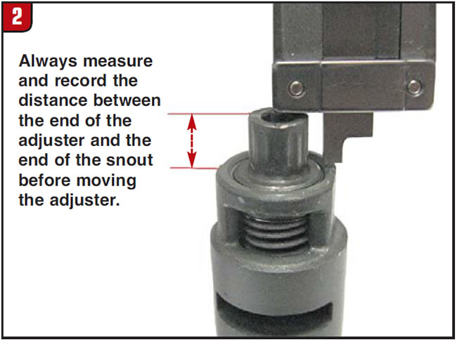
Caution – On AW55-50 solenoids, before moving the adjuster on the snout, remove the adjuster clip and measure from the end of the adjuster to the snout. Record the measurement for reassembly (Figure 2).
- Clean and dry all the parts.
- Remove the two solenoid bushing from the coil. A long, thin punch can be used, or if you have the bushing-installation tool it comes with a bushing-removal tool.
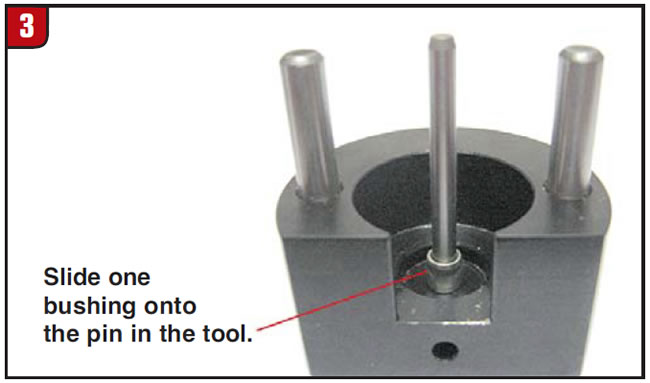
Installing the new bushings in perfect alignment:
- Place a bushing onto the small-diameter pin on the bushing-installation tool (Figure 3).
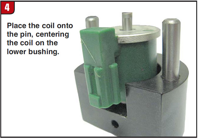
- Place the solenoid coil onto the small-diameter pin and center the coil onto the lower bushing (Figure 4).
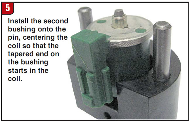
- Place the second bushing onto the small-diameter shaft and center the top bushing in the coil (Figure 5).
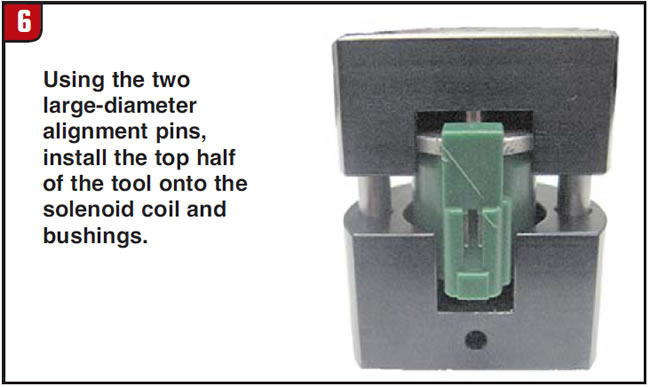
- Install the top half of the bushing tool, using the two large-diameter pins to align the tool halves (Figure 6).
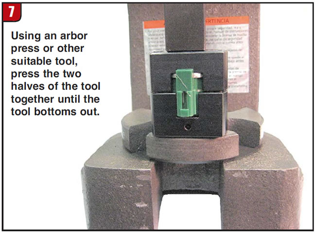
- Place the assembled tool in an arbor press and press the two halves together (Figure 7).
- Lift the top half of the bushing tool off and remove the coil and bushing assembly. Test the pintle in the new bushing. The pintle should move back and forth in the bushing under its own weight.
Inspecting the valve and snout:
- AW55-50 snouts have an adjuster at the end that can be removed to allow bore and valve inspection. Again, before moving the adjuster, measure and record. Look for damaged bores, stepped bores and bore wear. Note, the AW55-50 linear solenoid’s clearance between the snout and valve is loose when it’s brand new, usually more than you would expect to see on a worn bore.
- On TF80, TF81 and TF60 solenoids, there is a cap on the end of the solenoid that is staked in place. It is very difficult to re-stake the cap if it’s removed without damaging the cap or the snout. It is recommended that the cap NOT be removed from these solenoids. Instead, use a small punch pin to slowly move the valve back and forth in the bore, feeling for binding or sticking points. If the valve movement feels smooth with no binding it is OK to reuse.
- The valve should move freely in the bore without binding.
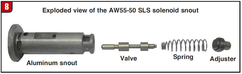
- Reassemble the valve into the snout, install the small end of the spring onto the valve stem and then install the adjuster (Figure 8).
- Reset the adjuster to the exact place it was, using the measurement that was taken before disassembly.
Reassembling the linear solenoid:
- Place the washer onto the stem of the pintle and insert the stem of the pintle into the coil with the new bushings. Double-check that the pintle moves freely in the bushings (Figure 1).
- While holding the pintle in the coil, position the coil into the new shell (Figure 9).
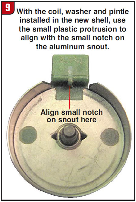
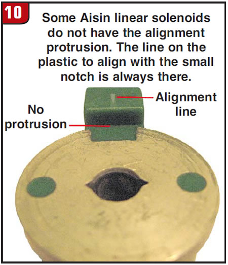
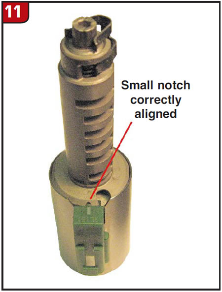
- Position the shell, pintle, washer and coil assembly into the base of the crimping tool. Place the snout onto the shell/coil assembly with the small notch in the snout aligned with the small plastic protrusion on the coil (Figure 10). Some late solenoids do not have the plastic protrusion. Instead, use the line in the middle of the plastic electrical connector to align with the small notch in the snout (Figure 11).
- While keeping the snout aligned with the coil, place the crimping tool onto the snout and press the tool down to hold everything together. Use a large arbor press to crimp the snout and shell together. The crimp must be tight so that there is no movement between the snout and the shell.
More information and cautions:
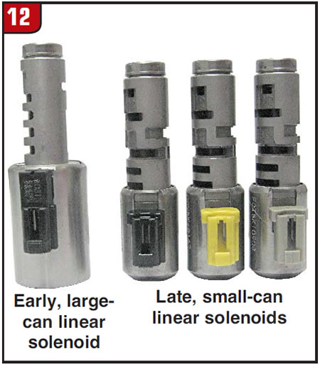
- The AW55-50, TF60/09G, TF80 and TF81 linear solenoids use the same bushings and outer shell. Some late TF60/09G use a smaller outer shell (Figure 12). The smaller-shell linear solenoids use different parts inside; the bushings for the larger-shell linear solenoids will not fit the smaller-shell linear solenoids on the TF60/09G.
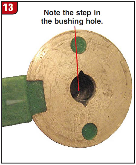
- Some TF81 brown-connector solenoids and TF60/09G yellow-connector solenoids have slightly smaller holes in the coil where the bushings go. The bushing hole at each end of the coil is stepped. It is a good idea to use a 6mm reamer to enlarge the hole down to the step before installing the bushings. Doing this will ensure that the pintle will not be tight in the bushings. Ream only to the step (step is just below the bushing) (Figure 13). Do not use a 6mm drill; it will grab and gouge the hole. The 6mm reamer is the best tool to use, as it will not be inclined to grab or gouge in the bore; the more flutes on the reamer the better.
- Rebuild only one solenoid at a time so that the parts do not get swapped around between solenoids.
Using this information should help you to rebuild linear solenoids for many miles of trouble-free operation.
Jeff Parlee is director of product support at ValveBody Xpress.