TASC Force Tips
- Subject: Valve-body and solenoid service
- Unit: AW 55-50/51 (AF23/33), TR-60SN/09D, TF-80SC/AF40, TF-81SC/AF21 and TF-60SN/09G
- Essential Reading: Rebuilder, Diagnostician
- Author: Bob Warnke
AW five-speed linear solenoids
In this article, the AW 55-50/51 five-speed (also known as AF 23/33) will be referred to as the AW 5.
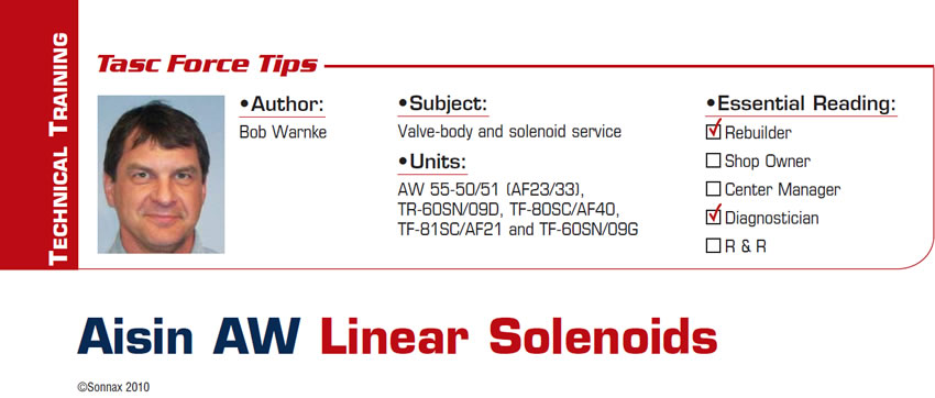
The AW 5 has three types of linear solenoids (Figure 1): SLU (black connector), SLT (blue connector) and SLS (green connector). Other on/off-style solenoids are used to control the position of the shift valves. The AW 5 uses linear solenoids to control line rise (SLT), the converter clutch (SLU) and the oil flow rate and accumulation for the clutch circuits (SLS). The flow-to and function of these solenoids overlap, which makes diagnosis difficult.
All three solenoids are supplied a regulated oil pressure through a solenoid modulator valve. The function of this valve is comparable to that of a GM 4T65-E/4L80-E actuator-feed-limit valve. In the AW 5, the solenoid modulator valve limits solenoid pressure to 90 psi. If you wish to verify the regulation point, tap into SLT pressure and perform a stall test. If SLT exceeds 90 psi, the solenoid modulator bore is worn at the inboard end.
Bore wear at the solenoid modulator can allow maximum pressure to be excessive, but it also can allow pressure to be lower than line pressure. For example, if there is bore wear at the spring end of the valve, line pressure could be 55 psi at idle, but feed to the solenoids could be reduced to only 40 psi. High solenoid-modulator pressure causes harsh, bumpy shifts and tie-ups. Low pressure creates flared/long shifts and poor TCC application. Although most AW six-speed solenoid functions differ from those of the AW five-speed, solenoid modulator function and related problems are the one thing they have in common.
AW 5 drivability
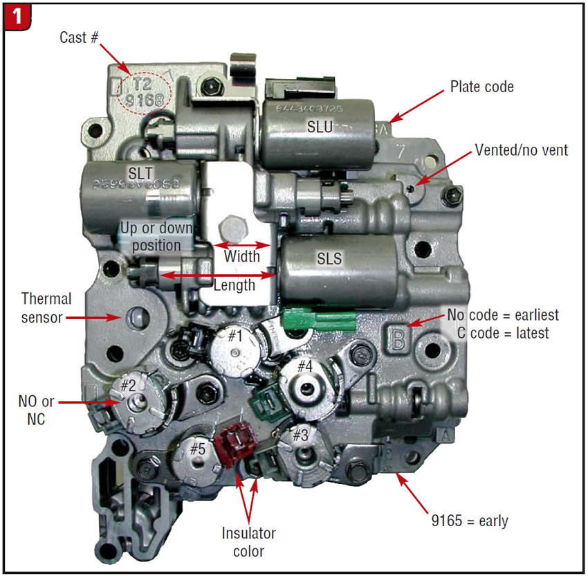
Figure 2 highlights the more-dramatic effects that different linear-solenoid malfunctions have on shift quality or torque-converter feel at various shift points. As a general rule, if all shifts are harsh, check line pressure first. Line rise is controlled by the SLT. If forward and reverse are harsh or delayed, the 1-2 is harsh and 2-1 coast-down firm, the concern is often related to the SLU. The SLU also affects TCC control after the 2-3 shift. When the SLU is out of adjustment, the TCC may cycle or result in a harsh gear change due to an inadequate release of the converter clutch. When there is a flared shift on multiple gears such as 2-3, 3-4 and 4-5, suspect the SLS because it is the flow-control solenoid.
AW 5 solenoid adjustments
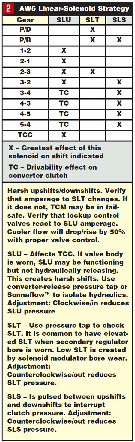
The adjustment screws on the AW 5 increase or reduce the spring force against the valve. The spring opposes the force of the coil (Figure 3). To avoid severe drivability issues, the adjuster should be set at or near the OE position, which averages 0.195 inch/4.9 mm measured from the end of the adjuster to the end of the solenoid manifold. If the adjustment is too far off – either in or out – various drivability issues occur. In many instances, an out-of-adjustment solenoid may cause the TCM to set a gear-ratio code or a solenoid-amperage high/low code.
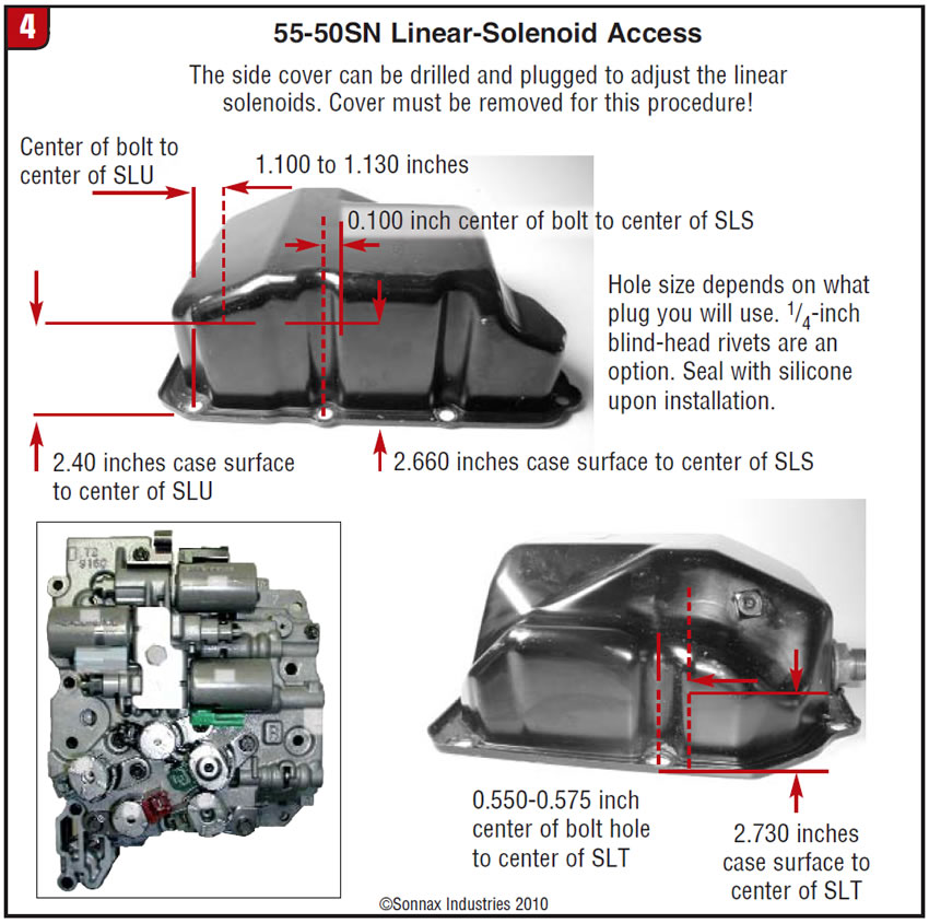
If the solenoids require an adjustment in the vehicle, access holes can be drilled in a cover to match the location of the adjusters (Figure 4). The holes can be plugged later with a blind-head rivet. In some vehicles, adjusting these on a hot transmission in a cramped compartment can be “uncomfortable.” One trick is to use a cover with speedometer cables mounted through it. These extend to the driver’s compartment for ease of adjustment.
Note: If the valve body is worn internally, a solenoid adjustment may improve operation at first but it will be only temporary.
AW 6 linear solenoids
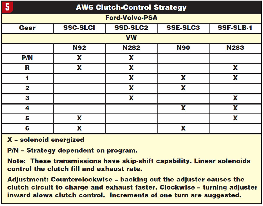
The following information applies to the entire Aisin AW six-speed lineup: TR-60SN/09D, TF-80SC/AF40, TF-81SC/AF21 and TF-60SN/09G. The TF-60SN/09G will be used as the example, because the valve body and solenoids tend to be more sensitive to calibration and adjustment. The chart in Figure 5 indicates the solenoid control strategy used in all the six-speed units.
Each clutch in an AW 6 is controlled independently by a dedicated linear solenoid. Source oil pressure for all the linear solenoids is regulated by a solenoid modulator valve.
The AW 6 does not use a typical clutch switch valve as in the AW 5. The AW 6 relies on the linear solenoids to control the application and release rate of each clutch. By reviewing the chart, you’ll notice how active the N90 and N282 would be in city traffic. Because of this drive cycling, one or both of these solenoids tend to hang up, resulting in rough coast-down shifts.
AW 6 drivability
It’s important to understand clutch overlap on the six-speed units. The timing of application and release of two to three elements has to vary according to load, engine speed/torque input, temperature etc. If the solenoid or clutch-control valve is slow due to wear or contamination, the TCM may not react or compensate fast enough to get the shift within parameters. Often these units can have severely harsh or flared upshifts or downshifts with minimal clutch damage. Valve-body and solenoid service will correct a broad range of complaints, but if the fluid is very dark, damage and wear may have advanced and internal repairs will be needed.
AW 6 in-vehicle service
On most AW 6 units, the valve body must be lowered onto longer bolts or pulled outward from the case to exchange solenoids. To help isolate which solenoid is slow, you can swap from a neighboring bore and, if the problem travels to a new clutch/position, it’s related to the solenoid. The adjusters that calibrate the solenoid and clutch-control valve are easily accessible. Within one to 11/2 turns, you should notice a difference in that clutch.
Bench testing
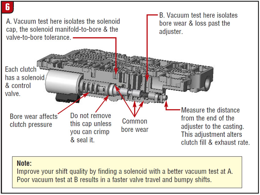
A common issue found in both the AW 5 and AW 6 is a hot drivability concern. This happens when the plunger starts to seize within the coil bushings at operating temperature. The results are acceptable shifts when cool but a harsh downshift or flared upshift (often 3-2 and 2-3) over the 215°F/85°C range. (Figure 6)
If you suspect this, a slow or sticking linear solenoid can be identified by a hot-soak test (figures 7 & 8).
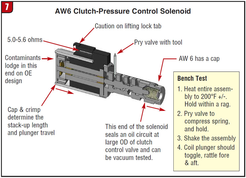
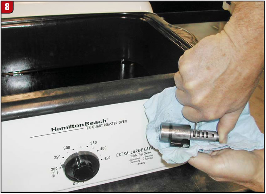
Heat the solenoid to operating temperature. Using a shop rag or some other method of protecting your hand from the heat, pry and hold the valve away from the plunger and shake the solenoid. In a good solenoid, the plunger shaft will be free to rattle back and forth.
Rebuild vs. new solenoids
This is a tough choice on most modern transmissions, and the need to address solenoid function becomes even more critical when linear solenoids are involved. On either end of the rebuilding process you will need to find a method to disassemble and reassemble the solenoids. In the middle of the process, effective servicing requires some basic equipment, including a demagnetizer, a hot tank, an ohmmeter and the proper method to energize the coil. Initial labor for each solenoid may require about 30 minutes to disassemble, clean, demagnetize, re-bush and reassemble. If you want to avoid the on-car adjustment process, you will need a solenoid test plate and a variable-frequency controller, plus a data-acquisition system to determine pass/fail parameters based on testing known, good solenoids. Fortunately, affordable new high-quality aftermarket solenoids are becoming available. For many, this option may prove the better choice than either developing your own full-blown solenoid-rebuild operation or trying to find good replacement solenoids from cores.
The AW 55-50 solenoids are generally calibrated as a set and then installed. It is very important to remember that – whether you rebuild your existing solenoids or install replacements – the valve body itself must be properly repaired as well.

Bob Warnke is Sonnax vice president of technical development and a member of the Sonnax TASC Force (Technical Automotive Specialties Committee), a group of recognized industry technical specialists, transmission rebuilders and Sonnax Industries Inc. technicians.
©Sonnax2010


