TASC Force Tips
- Author: Brian Wing
- Subject Matter: Hydraulic control
- Units: GM & ZF 6-speeds
- Issue: Operation & diagnosis
There are a growing number of transmissions on the road that incorporate a hydraulic control feature many technicians are unfamiliar with, though they may have noticed the involved components during many builds. Variations of this system can be found in GM and ZF six-speeds, many Aisin AW units and some Ford models. If you haven’t already, it’s an easy bet you will encounter malfunctions related to it sooner or later.
GM refers to it as the compensator feed circuit. Other manufacturers have their own names (ZF calls its system “dynamic pressure balance,” for example) and variations in operation, but basic function and desired results are similar from manufacturer to manufacturer.
Many builders and diagnosticians know that GM’s compensator feed system is used to assist return-spring force during disengagement of certain clutches; the operational details and additional functions may be less clear and are concepts that deserve further examination.
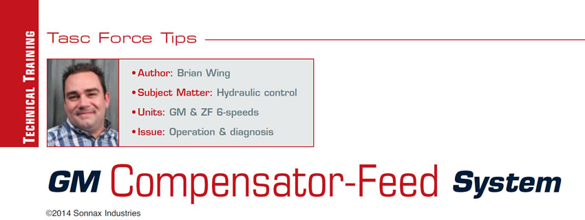
The compensator-feed circuit in rear-wheel-drive GM six-speeds is split into two sections: compensator feed and clutch-exhaust backfill. The backfill circuit is fed through an orifice from compensator feed. When clutches are not applied, the clutch-apply cavity is prefilled by the exhaust-backfill circuit. This allows the clutch pack to be applied more rapidly when commanded on (Figure 1).
But as the unapplied clutch assembly rotates, centrifugal force acts on the trapped backfill fluid and causes the clutches to partially apply. This is not a problem in the 2-6 and low/reverse-clutch assemblies because they are non-rotational, but the 1-2-3-4, 3-5-reverse and 4-5-6 assemblies require a method of preventing the clutches from dragging under these conditions.
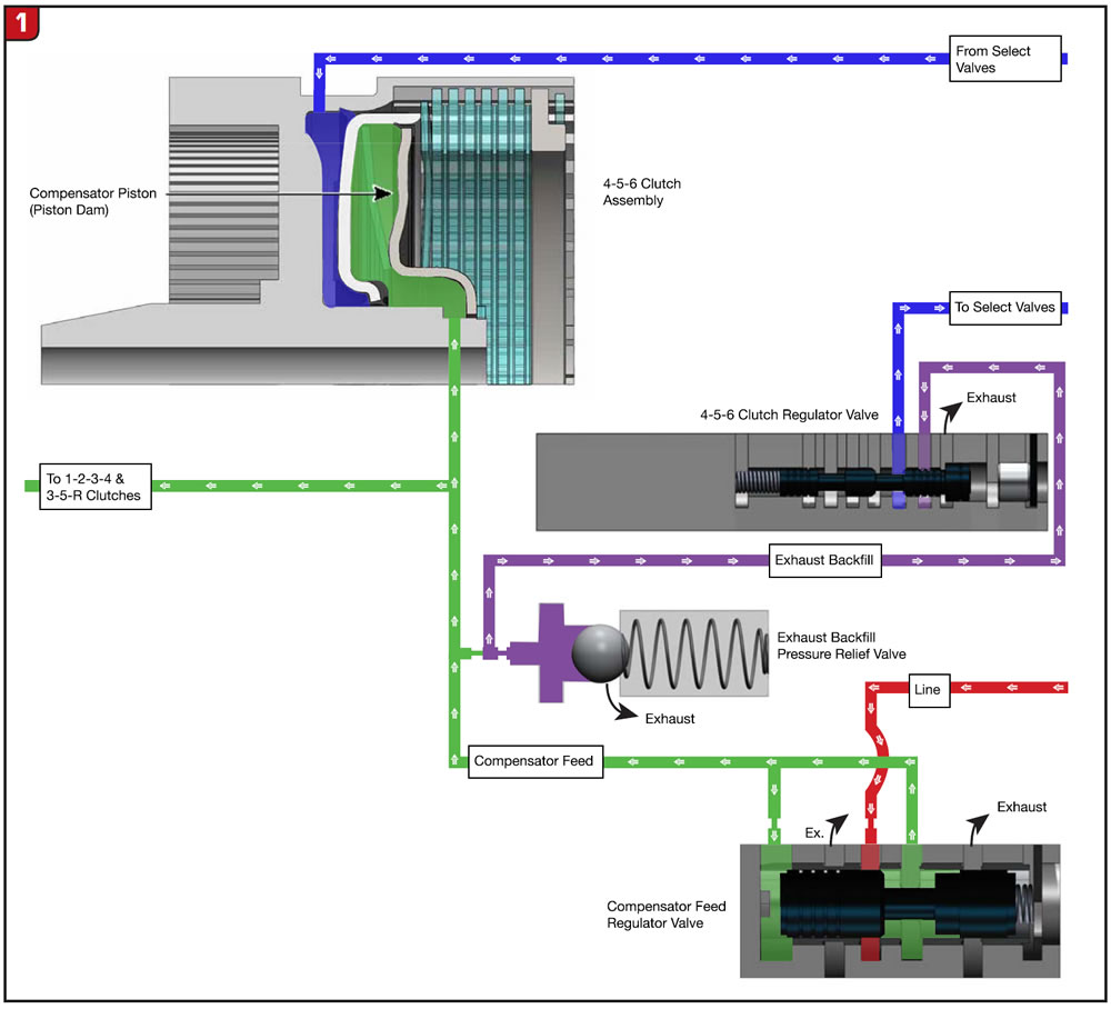
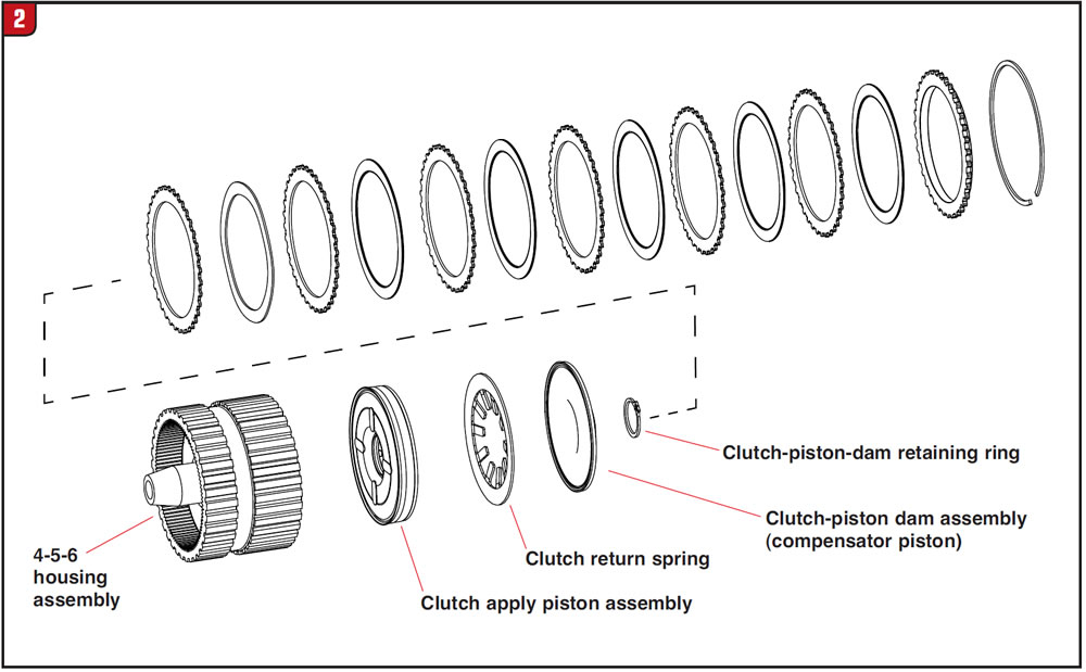
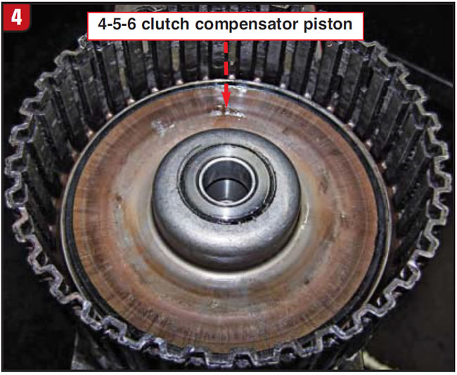
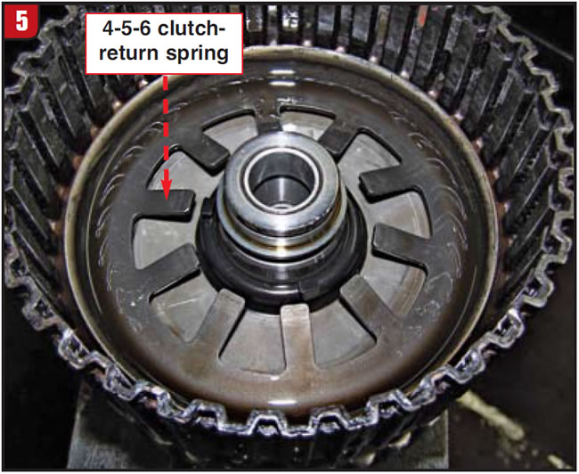
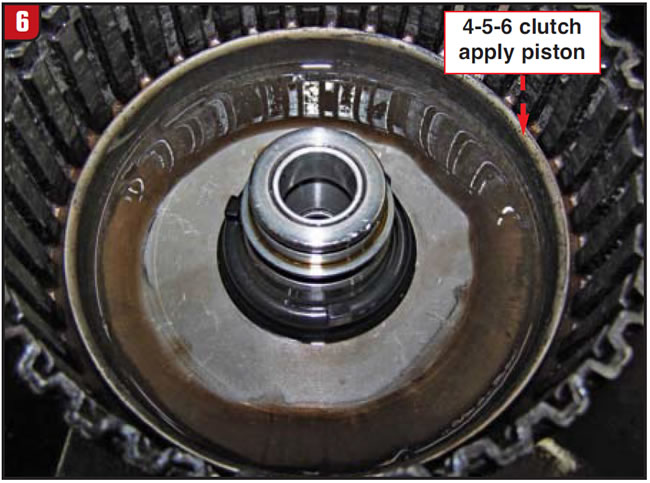
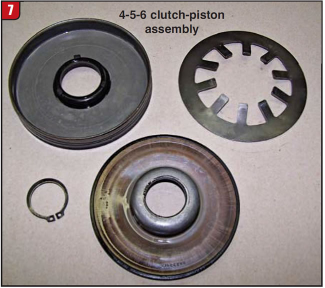
To achieve this, a compensator-feed regulator valve interacts with line pressure to direct low-pressure oil to the rotating clutch housings (Figure 1). Compensator pistons or “piston dams” are mounted inside the housings, between the clutch-return spring and the clutch pack (figures 2-7). The compensator piston holds a head pressure of about 10 psi against the apply piston to assist clutch release and prevent unwanted centrifugal apply.

When clutch actuation is desired, the regulating valve for the applying clutch controls both the apply rate of the clutch and the exhaust path for the exhaust-backfill circuit. A welcome benefit of this hydraulic interaction is an added accumulator effect during the shift.
Compensator-feed pressure causes more-rapid disengagement of clutches than return springs alone. With exhaust backfill allowing faster clutch application and compensator feed allowing faster disengagement, the control unit can more quickly and precisely manage overall operation of appropriate clutches, resulting in smoother overlap shifts.
So with these functions in mind:
- Assisting return springs
- Counteracting centrifugal apply
- Accumulation
- More-rapid clutch control for improved shift timing
It becomes apparent how malfunctions in the compensator-feed circuit negatively affect transmission operation. A worn or sticking compensator-feed regulator valve can cause slower or faster clutch action than desired, resulting in:
- Bump shifts
- Bind-ups
- Flares
- Downshift clunks
- Harsh shifts
- Burned clutches
- Overheated fluid.
A compensator piston that has lost its sealing ability can give rise to the same concerns.
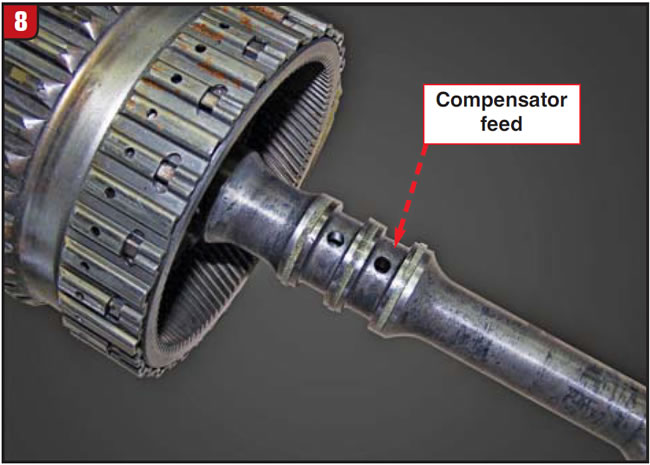
In the case of the 4-5-6 clutches, compensator-feed fluid is routed through the turbine shaft (Figure 8). Failed shaft sealing rings will permit exhaust of compensator fluid and allow the clutches to burn up in a partial apply. If you get smoked 4-5-6 clutches soon after a rebuild, check the seals to make certain they were not inadvertently cut or damaged during installation.
Compensator-feed oil from the 4-5-6 clutch assembly is also fed through an orifice to lube the rear case and extension bushings. Any lubrication failures here will require a look at the compensator-feed circuit as a possible suspect.
With these units, investigating clutch failures must include views from a different angle. We are accustomed to searching for a problem in the apply circuit when diagnosing burned clutches, expecting to find a cracked drum or apply piston, leaking accumulator, worn clutch-regulator valve/bore etc. When the cause of burned clutches cannot be traced to issues on the apply side, it’s time to examine the compensator-feed circuit for failures or worn components.
There is no pressure tap, which leaves us without one piece of the diagnostic puzzle. It pays to look at the compensator-feed regulator valve in particular, because it oscillates continuously and strokes in such a small range that wear is a problem. If you carry out vacuum or wet-air testing, you will find many of these valves underperforming and in need of replacement. If you aren’t in the practice of vacuum or wet-air testing, it’s a good idea to replace the regulator during every build to prevent comebacks and prolong the life of your build.
Some non-GM units, such as TF-60SN and AW 55-50SN, use similar systems with operational differences. For example, these transmissions don’t use a dedicated regulator valve; instead, the primary and secondary pressure-regulator valves feed oil from the lube circuit to a “balance” piston to achieve the same results as GM. These valves should also be vacuum-tested and replaced as necessary to ensure proper circuit operation.
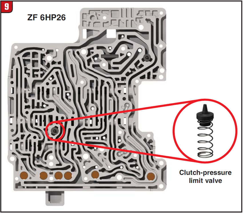
A universal necessity regardless of manufacturer is circuit-pressure relief. GM uses an exhaust-backfill pressure-relief checkvalve and spring in the valve body to protect against over-pressurization (Figure 1). Manufacturers that use lube for this circuit, such as ZF, employ a similar pressure-limiting valve (Figure 9).
The compensator-feed circuit is a straightforward and relatively simple system that has a definite effect on proper transmission operation. Remembering this during diagnosis and rebuild will prevent comebacks and pay customer-loyalty dividends on a job well done the first time.
Brian Wing is a Sonnax technical writer/technical-support specialist and a member of the Sonnax TASC Force (Technical Automotive Specialties Committee), a group of recognized industry technical specialists, transmission rebuilders and Sonnax Industries Inc. technicians. E-mail Sonnax Tech Support at [email protected] or call 800-843-2600. ©2014 Sonnax Industries


