Fixing JF011E primary pulley pressure sensor issues

Fixing JF011E primary pulley pressure sensor issues

A 2.4L Dodge Caliper using a JF011E CVT2 transmission developed a problem with the Primary Pulley Pressure sensor. A low circuit error code P0842 was pulled from the TCM. The sensor ground and 5-volt wiring circuits were checked and verified as good. The signal wire was then inspected and was also verified as good.

There was a hope of finding a short or break in this wire making for a simple repair. With the integrity of the wiring being verified as good, the pan was pulled for inspection. The amount of debris on the magnets was somewhat typical and yet still enough to be concerned that there may be pulley damage. So, the valve body was removed to get a view of the primary pulley sheave face and the condition of the push belt. Everything looked very good.

At this point the technicians decided to change the Primary Pulley Sensor. When they discovered that a good known sensor could not be found, a new valve body and ROM assembly was ordered according to vehicle’s identification number.

Once the valve body was replaced, this continuously variable ratio transmission was reduced to one ratio only. A scan tool revealed that P0842 was no longer being set, but there was a new code in the system: a P0730 for incorrect gear ratio.

A stepper motor is used to control the ratio control valve in the valve body via a lever that indexes to the primary pulley follower. Since a new valve body was installed which would include a new stepper motor, the chance of the stepper motor being defective is slim. However, as we all have learned in the past, new does not necessarily mean good. And with that in mind, the valve body was pulled to check the stepper motor. The problem began to reveal itself during the removal process of the valve body.

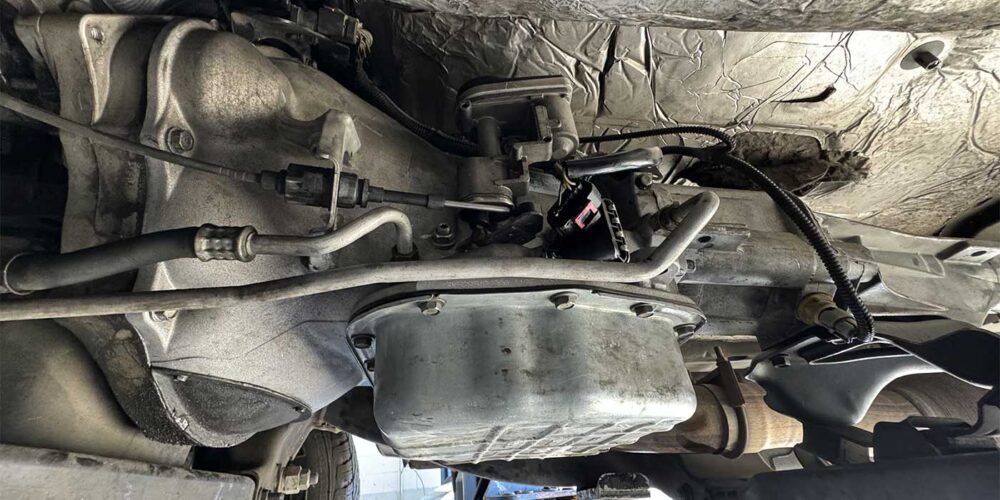
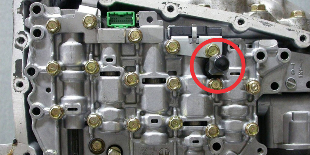
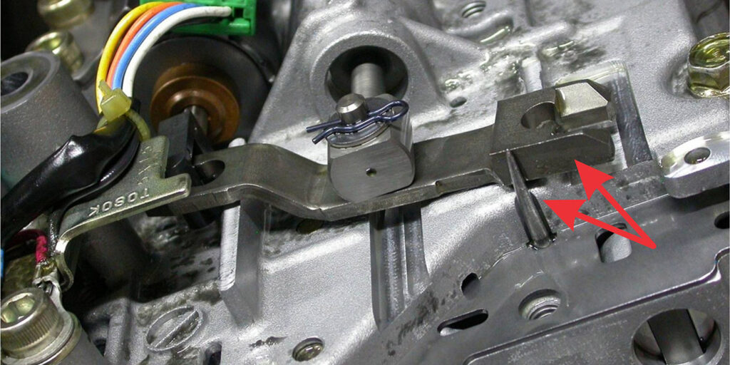
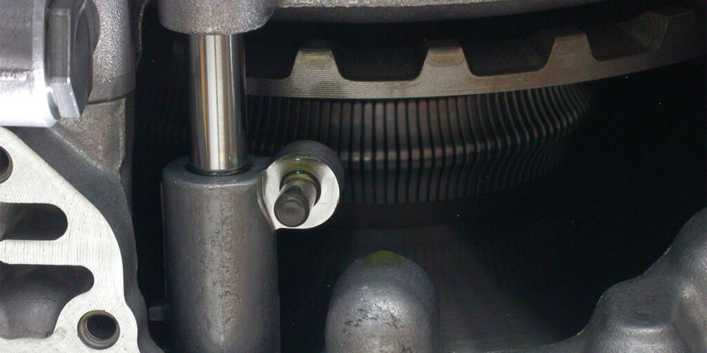
Going through the valve body is an access hole designed to be used with a tool with which to hold in place the ratio control valve assembly during both the removal and assembly process. Figure 1 (above) is a view of a handled pic already inserted into this access hole. Figure 2 shows the valve body being removed with the pic in place.

Figure 2.

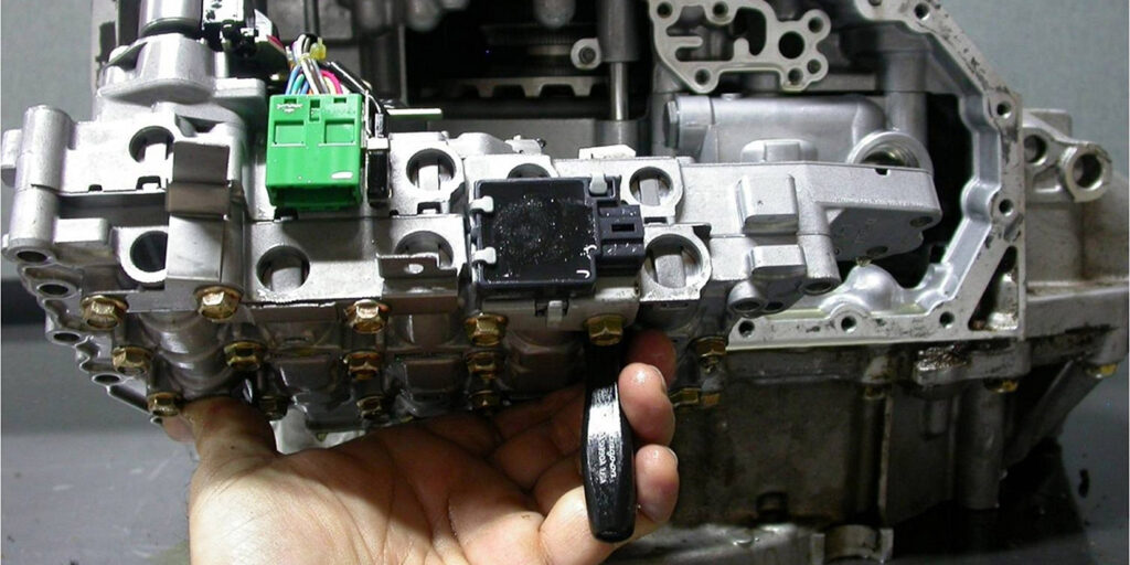
Figure 3 is a close-up view showing the tip of the pic holding the ratio control valve lever in place. This is also the proper position of the lever for when installing the valve body.

Figure 3.

The end of this lever that the tip of the pick is up against indexes to the primary pulley follower as seen in figure 4. Figure 4 also shows how the Stepper Motor is linked into the opposite end of this lever. In between the lever is the ratio control valve going into the valve body. This is a spring-loaded valve, so there is a small amount of tension on the pic due to this spring.

Figure 4.

During the removal of the valve body to inspect the ratio control motor, when a pic was inserted into the hole, it was being blocked from its complete insertion. This provided a clue as to what the problem was. When the valve body was removed, the problem became evident. Apparently, during the installation process, the pic used to retain the proper position of the lever pulled out far enough to allow the spring tension on the valve to mis-position the lever. When the valve body was bolted into place, the pin on the pulley follower was jammed against the lever. Figure 5 shows how the pin was pushed halfway through the follower. This prevented the stepper motor from moving the ratio control valve to ratio the transmission.

Figure 5.
Figure 6.

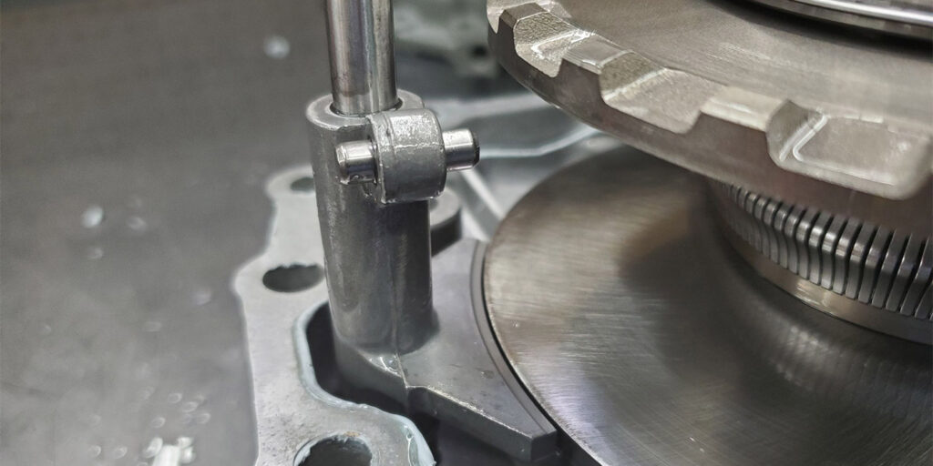
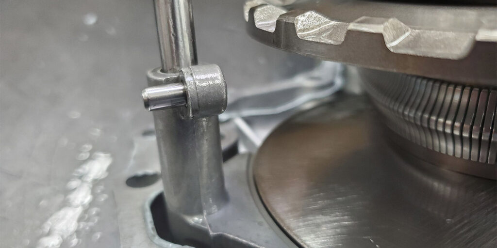
Figure 6 shows the way the pin should always be mounted in the follower assemble. To correct this error, the unit needed to be removed and disassembled. Not a good day to say the least; unless of course the customer is happy to have a one ratio CVT.

You May Also Like

Shift of the shaft: Diagnosing Chrysler 48RE manual shaft issues

The TorqueFlite transmission has been around since mid-to-late 1950s. There have been many changes surrounding the manual shaft and rooster comb through the years. This transmission shaft controls the position of the manual valve that directs oil for the gear ranges, but it also is used for a Reverse light control as well as Park/Neutral

The TorqueFlite transmission has been around since mid-to-late 1950s. There have been many changes surrounding the manual shaft and rooster comb through the years. This transmission shaft controls the position of the manual valve that directs oil for the gear ranges, but it also is used for a Reverse light control as well as Park/Neutral safety control. As it evolved, changes to these safety backup switches caused extra stress against the rooster comb that posed new challenges to the technician. 

Sometimes, a diagnostic code is all you need

With ATSG having the opportunity to help shops solve problems, sometimes we get faced with some real doozies. A shop will call and give us a laundry list of DTCs, leaving us to think someone must have a bulkhead connector unplugged. We then go through the arduous task of deciding which codes prompted other codes

10L80 and 10R80 pump gear differences

You may have seen an article in the August 2023 issue of Transmission Digest called “GM 10L80: A new kind of pump noise,” which goes over how the front cover housing in the 10L80 is fitted with a converter drive gear and idler gear. The idler gear drives the pump’s driven gear, and is press

Shift Pointers: What to do when the 62TE TRS tab breaks

How frustrating it is when on a hot summer day, as you go to open a nice cold can of your drink of choice, and the tab breaks off? You are outside, away from any tools to remedy the problem quickly. It now requires a MacGyver mentality looking around at the resources available to get

Going the extra mile: Proving your transmission repair suspicions

A 2003 Honda Pilot with a five-speed three-shaft transmission came into our shop with a customer concern that the vehicle had no power, and the “D” light was flashing. I first did a scan for codes to see what it came up with, and the scan tool returned four DTCs: P1298 (ELD voltage high), P0135 (H02S

RRfeature-1400

Other Posts

Spotting different 68RFE designs through the years to avoid issues

The Chrysler 68RFE has had several changes through the years. Its four-speed predecessor began with a noisy solenoid pack identified by a black colored pass-through case connector (seen in Figure 1).  Related Articles – Outgrowing the walls: The story of EVT Transmission Parts – Valve body and component suppliers: A comprehensive list – Shift Pointers:

Shift Pointers: Failures caused by incorrect tire sizes

For years ATSG has produced a wide range of issues related to improper tire sizes on vehicles. Even under-inflated tires have been known to cause issues. Problems such as premature failure with an active 4WD transfer case will occur with incorrect tire sizes. Related Articles – Understanding lube flow control valves in Toyota/Lexus UA/UB80 transmissions

Shift-Pointers-Jan-Figure-1-1400
Understanding lube flow control valves in Toyota/Lexus UA/UB80 transmissions

The Toyota/Lexus UA80 and UB80 transmissions first came out in 2017 in Highlanders and Siennas. The UA80 is used in V6 applications, and the UB80 is paired with four-cylinder versions. They have been called Toyota New Global Architecture type transmissions, and alternately referred to as the “Direct Shift 8AT” eight-speed automatic transmission. This transmission was

Tasc-Tip-December-Figure-1---LFC-Valve-OE-Partial-Circuit-Diagram-1400
How reading through service bulletins can turn a technician into the customer’s hero

Over the last 28 years of being a technician, I have developed the habit of checking for and reading technical service bulletins at the forefront of the diagnostic process, especially when an unfamiliar vehicle exhibiting blatant or straightforward concerns comes into the shop. I have found many valuable nuggets of information while reading over these