Technically Speaking
- Subject: Replacing electrical components and/or valve body
- Unit: JF011E/RE0F10A
- Vehicle Applications: Dodge, Mitsubishi & Nissan, 2007 up
- Essential Reading: Rebuilder, Diagnostician
- Author: Wayne Colonna, ATSG, Transmission Digest Technical Editor
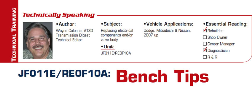
The JF011E/RE0F10A (Figure 1) is a continuously variable transmission used in Dodge, Mitsubishi and Nissan vehicles as far back as 2007. These units have been increasingly visiting the shops for a variety of reasons. Some issues are repairable, but at other times the unit needs to be replaced. In some instances, electrical components and/or the valve body needs to be removed or swapped over to another unit. This article will provide some tips making this process a bit easier and pointing out some of the mistakes that others have made so you can avoid these self-inflicted injuries.
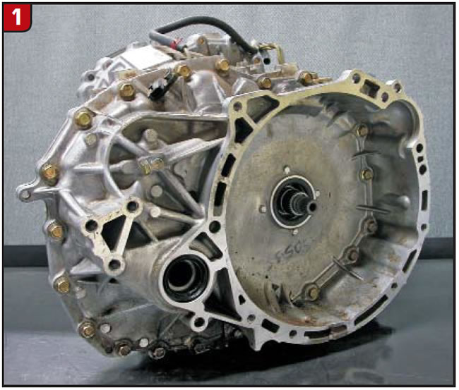
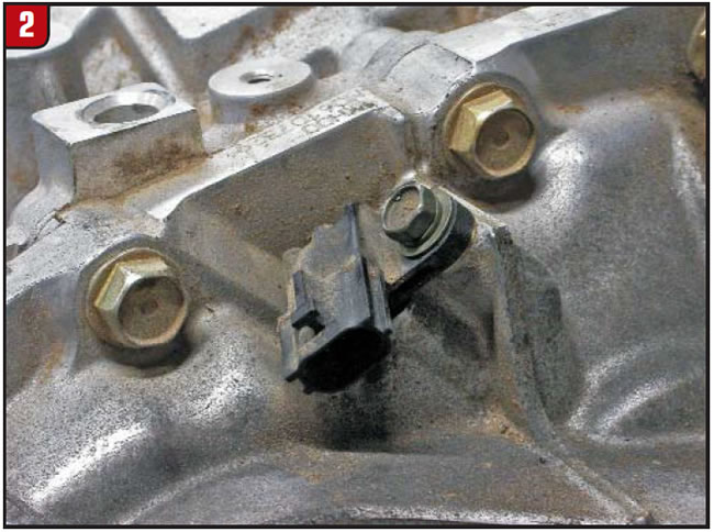
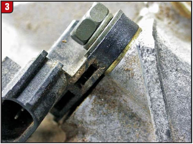
The first tip involves removal and re-installation of the output-speed sensor (Figure 2). A 0.040-inch shim between the Hall-effect sensor and the case sets the proper air gap between the sensor tip and output gear (Figure 3). It is very easy for this shim to fall away unnoticed when the retaining bolt is removed (Figure 4). If this sensor is installed without the shim, the sensor tip just about touches the gear. This will produce a code for the sensor and possibly damage the sensor, requiring replacement with a new or good used one.

The next tip deals with removal and re-installation of the valve body. Whether you’re changing the valve body while the transmission is in the vehicle or on the bench, it can be a little difficult and may produce new problems, all of which you can avoid by knowing just a few simple procedures.
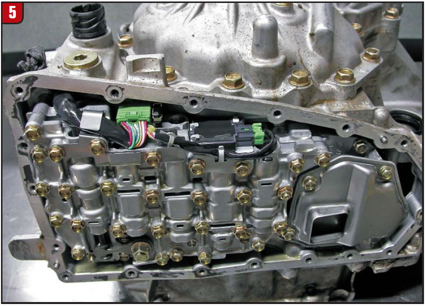
Figure 5 shows the transmission with the converter housing face down on the bench and the pan removed. This allows a good look at the 22-pin case connector, internal wiring harness and ROM.
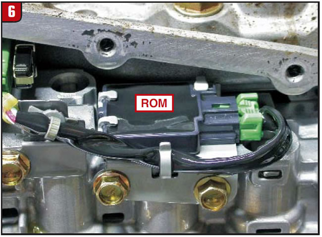
This ROM (Figure 6) is programmed with calibrated information matching the TCM. If a different ROM is used during a transmission exchange in a 2008 Dodge Caliber, for example, a P167A code will occur for a calibration mismatch. Resolving this problem would require a reprogramming procedure or putting the original ROM back in. It seems that at this time only Dodge can reprogram the ROM and TCM to match, whereas Mitsubishi and Nissan require a new one to be ordered via the VIN. If you choose to keep the original ROM with the vehicle during a valve-body or transmission exchange, be sure to mark the ROM with a tag to avoid any confusion.
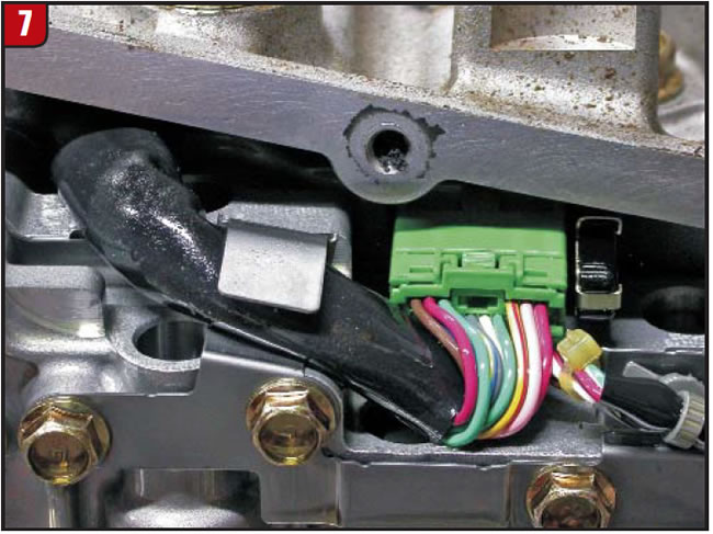
The valve body can be removed with or without the 22-pin case connector and wiring harness. I find it easier to remove the valve body without this part of the wiring harness, especially when it comes time to install the valve body, which we will cover shortly.
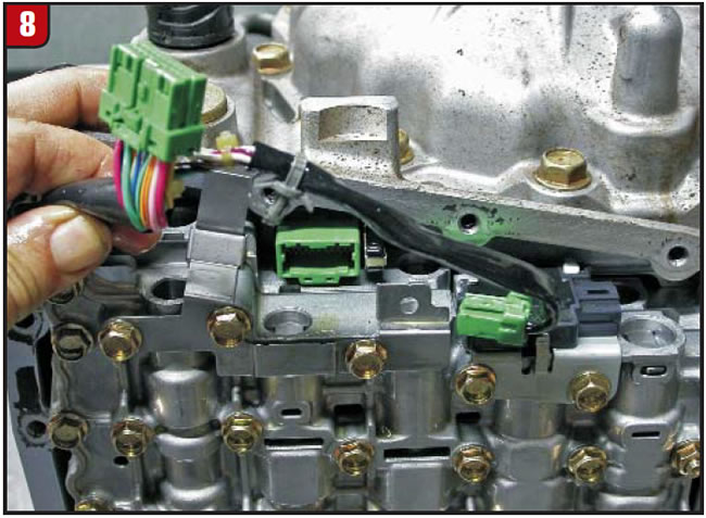
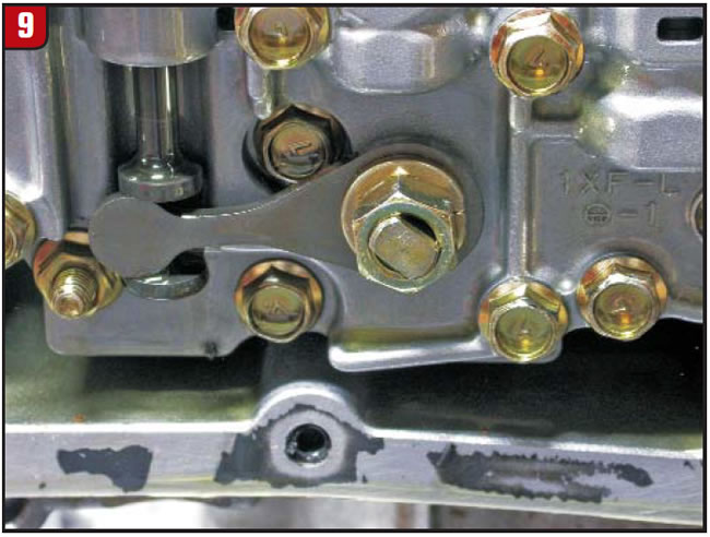
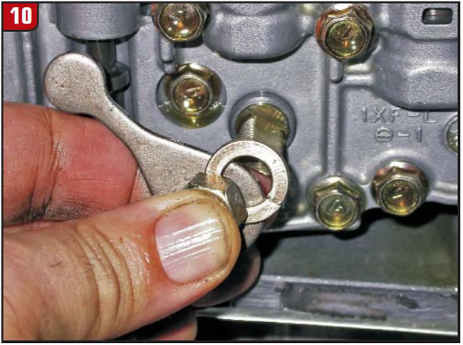
To remove the valve body without the harness, simply open the harness hold-down bracket (Figure 7). Unplug the ROM and the main internal harness connector and place the harness clear of the valve body (Figure 8). The next step is to remove the manual lever from the shaft (figures 9 and 10).
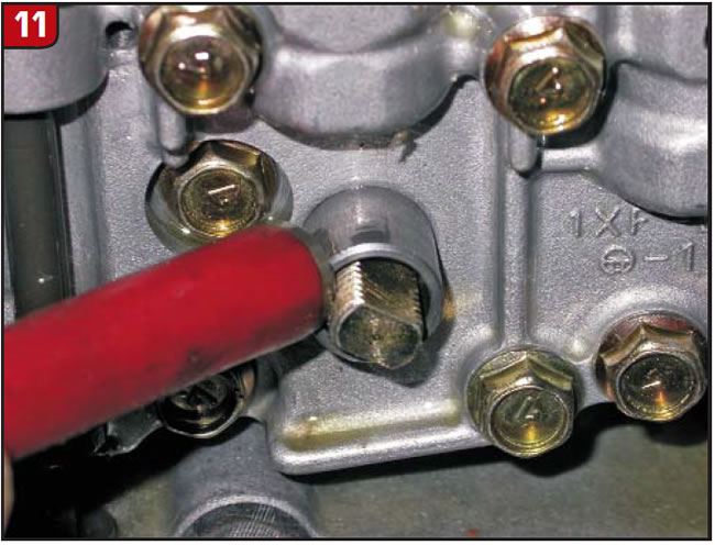
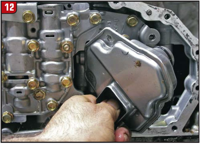
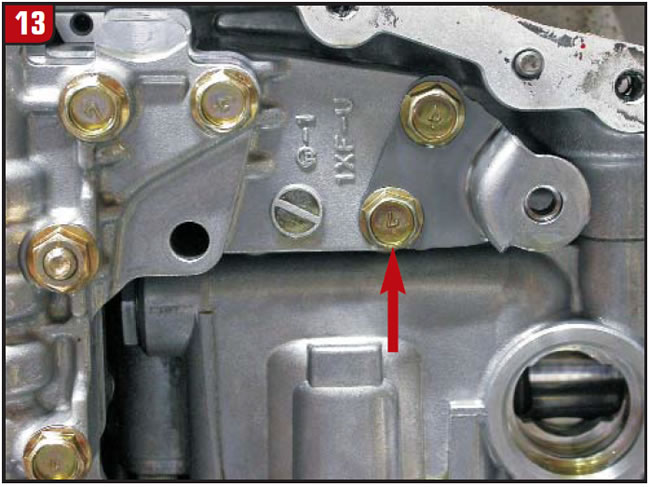
If this is being done in the vehicle, be careful not to lose the manual-control-shaft sleeve (Figure 11), as gravity may cause it to drop out unnoticed. If you’re doing this on the bench, get a good magnet and remove the sleeve before it gets lost. Next, remove the filter (Figure 12) and the filter support bracket (Figure 13) from the valve body.
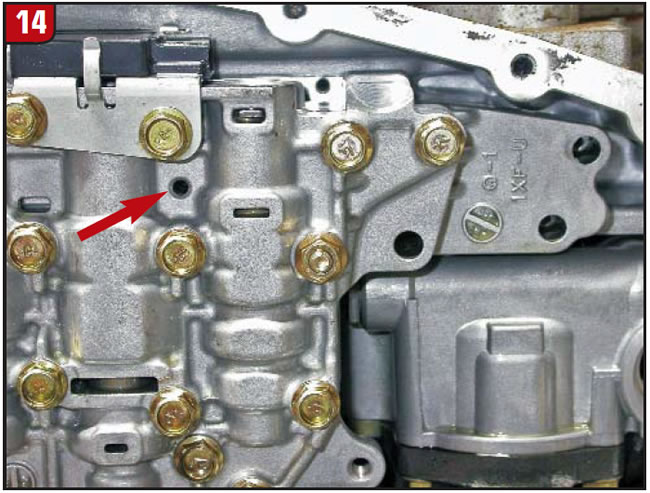
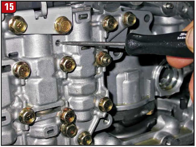
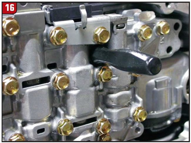
After removing the filter support bracket, locate an access hole in the casting of the valve body to the left of the bracket (Figure 14). Insert a rod 3mm (0.120 inch) in diameter and 126mm (5.0 inches) long into this hole (figures 15 and 16). This will retain the pulley-ratio lever and prevent the spring-loaded ratio-control valve from coming out of place while you remove the valve body.
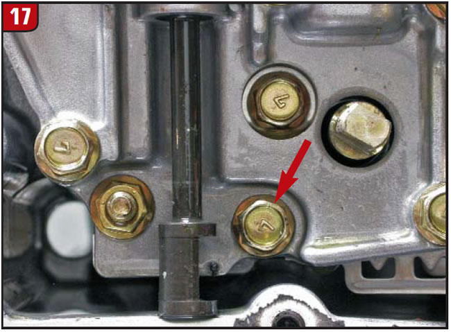
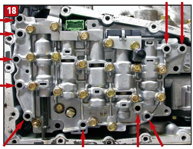
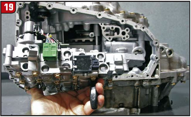
There are 11 bolts holding the valve body to the case. Remove the one short bolt by the manual valve (Figure 17) first, followed by the 10 longer outer-perimeter bolts identified by the arrows in Figure 18. Once the bolts are removed, carefully lift the valve body from the case while holding in place the rod that is securing the ratio-control-valve assembly (Figure 19).
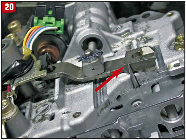
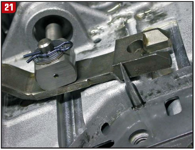
With the valve body down, you can observe how the retaining rod held back the pulley-ratio lever (figures 20 and 21). The opposite end of this lever fits into the ratio-control motor. The center of the lever is connected to the spring-loaded ratio-control valve in the valve body.
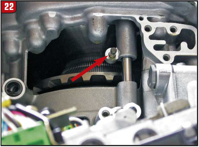
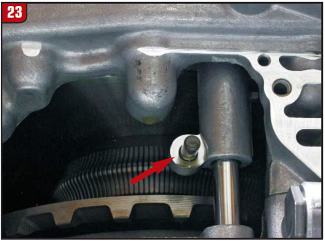
The end of the lever that the rod made contact with during the removal of the valve body indexes with the pin on the primary-pulley follower (figures 22 and 23).
This spring-loaded follower rides on the movable drive-pulley half and reacts to the movement of the drive pulley as it changes ratios. With one end of the lever being in the ratio-control motor and the other end being in the drive-pulley follower, the follower acts as a movable pivot point for the lever. In doing so, it becomes a mechanical sensor influencing the variable-ratio-control valve tailoring the feed fluid into the drive-pulley piston.
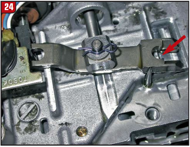
During installation of the valve body, this lever (Figure 24) must get indexed to the pin on the follower (figures 22 and 23); otherwise, the transmission will not shift and various codes will set.
The primary-pulley and secondary-pulley assembly in its static position is low gear. The belt will be on the smallest wrap of the primary pulley and on the largest wrap of the secondary pulley.
Inserting the rod through the access hole to hold back the lever holds the lever in the correct position to get it indexed to the pin on the follower. This is one of the reasons why I prefer not having the 22-pin connector and harness on the valve body to contend with. Trying to index the pulley follower and get the connector through the case all at the same time is like trying to get 10 monkeys together for a picture. But having knowledge of these simple procedures will get the job done right, easily.
One last point: I was speaking with a friend in the business, Bob Nuttal, who has seen technicians use a short rod to hold the lever back and then forget to remove it from the valve body. This, of course, will cause a no-shift complaint with a variety of codes, just as if you had missed indexing the lever to the follower pin. He suggests using a rod long enough that it is too obvious for you to forget to remove it. Thanks, Bob!


