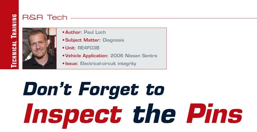
R&R Tech
- Author: Paul Loch
- Subject Matter: Diagnosis
- Unit: RE4F03B
- Vehicle Application: 2006 Nissan Sentra
- Issue: Electrical-circuit integrity
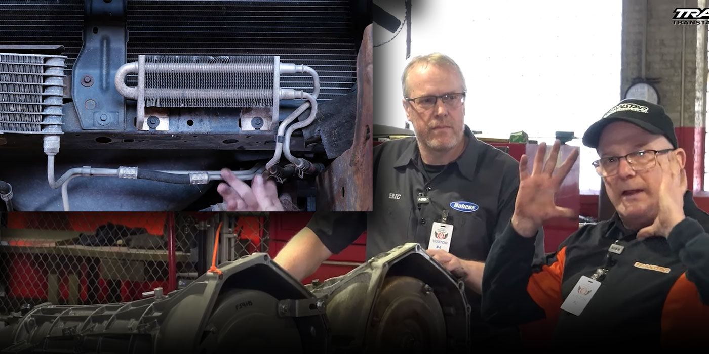
There once was a time when transmission installations were a very basic operation. Remember when fighting with rusty exhaust bolts was the biggest challenge you faced during an R&R? Well, until the engineers started hanging wires all over these modern cars, this may have been true. The game has changed – permanently.

When it comes to diagnosing vehicle issues in today’s world, so many things must be taken into consideration. You must check the integrity of all possible components that affect the subsystem you’re diagnosing. In the realm of modern automotive transmissions, those subsystems will include computer hardware, software, wiring, sometimes cabling and actuators, and the components on and in the transmission itself. I guess those old rusty bolts weren’t such a challenge after all.
Notice that I used the word “integrity.” For the purposes of this article, integrity can be defined as a correctly functioning component or system. It might look OK from a visual standpoint, but is it really doing what it’s supposed to? When it comes to evaluating a customer concern, you must confirm integrity.
A customer brought a 2006 Nissan Sentra equipped with a RE4F03B into our shop concerned that the transmission was not shifting at all. A road test to confirm the concern revealed nothing at all. The transmission shifted normally throughout the entire 10 miles driven. Back at the shop, a quick visual inspection also revealed nothing out of the ordinary.
After connecting the scanner to the vehicle and checking codes, we retrieved a P0750 (shift solenoid valve A) code. Checking this code against the service manual revealed that it is generated by a circuit issue. This means that the code is being generated because of electrical, not mechanical, problems. It is always important to determine whether the issue is electrical or mechanical in nature. Failing to make this determination early on will lead you down the wrong diagnostic path.
Since we were dealing with an electrical issue, it was first necessary to determine where possible causes could lie. The code definition says, “P0750 is set when TCM detects an improper voltage drop when it tries to operate the solenoid valve.” Translation: The issue could be within the solenoid windings, harness, connectors or TCM.
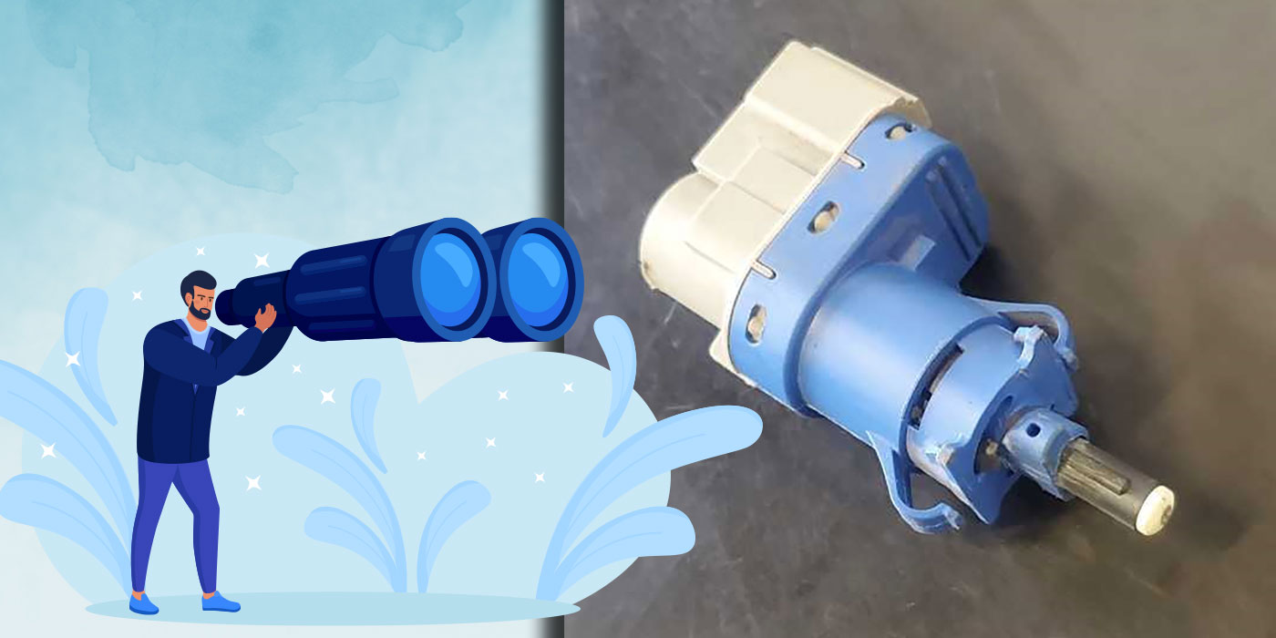
Starting with the solenoid itself, some electrical checks were in order. Normal resistance for this solenoid is 20-30 ohms. Since resistance measured 25 ohms, we ruled out the solenoid windings as a cause for the code. A resistance check between the case connector and the solenoid also checked out normally, as did a check from the case-connector harness to the TCM harness.

With the integrity of the solenoid, wiring and connectors appearing to be intact, the TCM became suspect. Not wanting to take anything for granted, we needed to determine whether the TCM was actually making the effort to control the solenoid before we could condemn it as the root cause of the issue. Another road test was in order to monitor the TCM’s shift-solenoid output in question, using the scan-tool PID (parameter identification data). Realizing that the transmission was shifting properly on the first road test, we didn’t really expect to see much on the second road test.
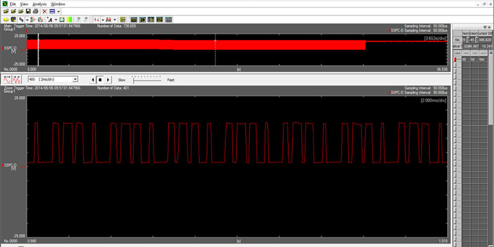
While monitoring the SSV A PID, we set off on a road test. We didn’t drive very far when the TCM suddenly went into transmission failsafe mode. Despite this, the PID revealed that the output from the TCM was there; it was at least trying to control the solenoid. That didn’t necessarily let the TCM off the hook, but it appeared that the logic circuits were working as programmed. The possibility still existed that the TCM drivers weren’t up to task and that the signal from the TCM to the solenoid wasn’t there.
We decided to check the TCM output voltages at the case connector to ensure that the TCM was capable of delivering the switching signals. No problems were detected there, so we could now safely rule out the TCM as a possible cause.
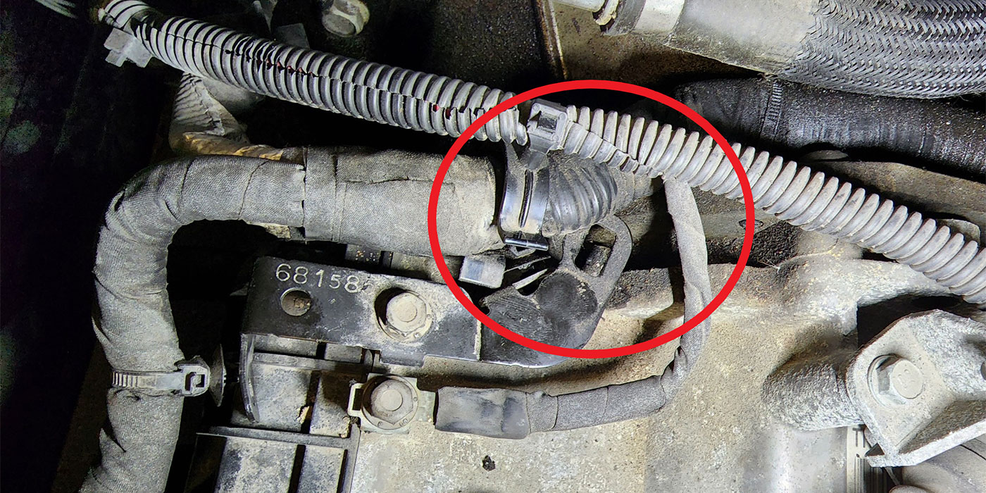
Reviewing what we’d checked already, we now needed to take a closer look at the circuits themselves. Since we’d already checked the wiring, we needed to look over the “unions” in the circuits: the pins that connect to each other in every connector on the vehicle.
Think of electricity as flowing water. If you have a solid pipeline that interconnects sections with unions, what would happen if a union were loose or disconnected? You would lose pressure and volume on the other side of the union.
One of the “unions” in our case – the case-connector-to-harness pins – did not have the integrity needed to carry current to the shift solenoid. Checking the pin drag at this location revealed a single pin that was just loose enough to have an intermittent connection. This loose connection was generating the P0750 code and creating the failsafe condition.
Resetting the pin drag by crimping the terminal a bit solved this case, but this story is a common one. It’s easy to overlook what you can’t see. I recommend that you check pin drag during any R&R job. Simply rocking the case connector during removal can cause a loose-fit issue. Checking this often-overlooked area will ensure that your customer leaves your shop with confidence.
Paul Loch is a diagnostician at Certified Transmission’s retail location in Bellevue, Neb. He joined the company as an R&R technician in 2010 after many years of experience in the general-repair industry.