Shift Pointers
- Subject: Operation of pressure-control solenoids
- Unit: Ford 5R55S/W
- Essential Reading: Rebuilder, Diagnostician
- Author: Jesse Zacarias
The 5R55S/W transmission has been with us for a little more than a decade. Its common complaints include harsh forward engagement; harsh reverse engagement; delayed, harsh initial engagements; flares on the 3-4 shift; and bind-up on shifts.
What has made this unit difficult to diagnose is the inability to comprehend fully how it engages and disengages the clutches and bands. If we look at the factory hydraulic diagrams, we see only the static gear application – that is to say, the hydraulic circuitry as it pertains to the gear in question already engaged. What we don’t see is the transition period, the steps between the static applications. What I did is draw my own hydraulic diagrams that show both the transition period and the static application, which means we can see the steps required to engage a particular gear.
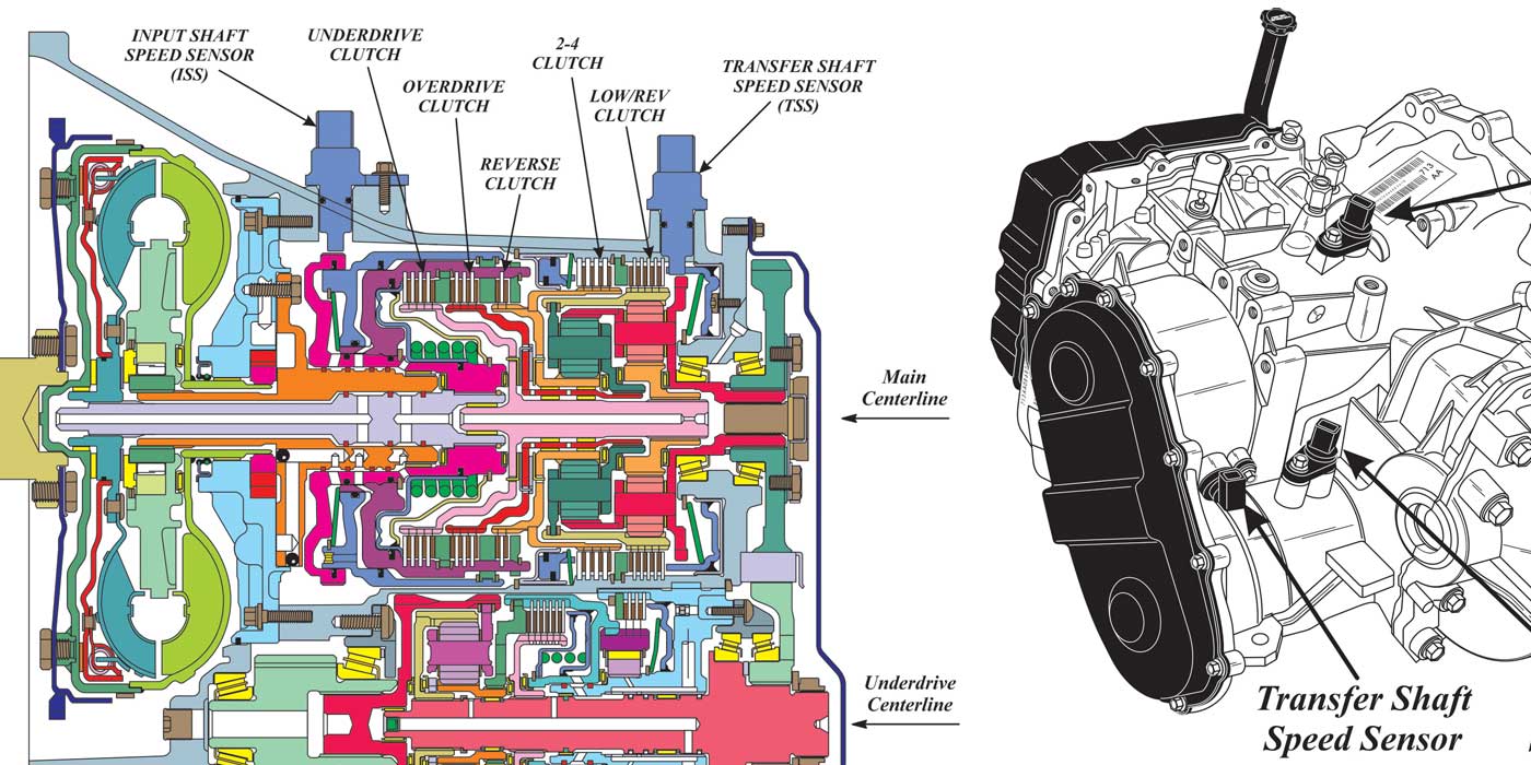
This transmission contains four on/off shift solenoids, one pulse-width-modulated (PWM) solenoid for TCC control and three variable-force solenoids. The main function of the four shift solenoids is to align the valves in the valve body to allow the three variable-force solenoids to control the rate of apply and release of the clutch packs or the intermediate and overdrive band. The PWM solenoid controls the torque-converter clutch (TCC). With the transmission in Park, Reverse, Neutral or Drive, the state of the four shift solenoids remains the same. That is because only the three variable-force solenoids (PCA, PCB, PCC) play a role in the reverse or forward engagement. Let’s look at the reverse and forward engagements.

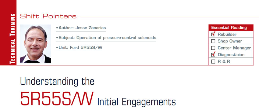
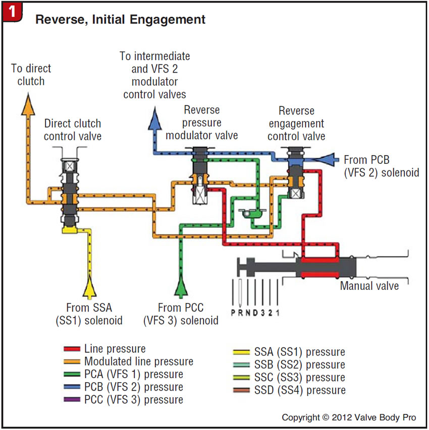
When Reverse is selected (Figure 1), the transmission range sensor sends a signal to the power control module (PCM) that the transmission was placed in reverse (Figure 2). The PCM then modulates variable-force solenoid 2 (PCB) with about 0.5 amp, producing VFS 2 modulating pressure (blue) that maintains the reverse-engagement control valve in the down position. This prevents main line pressure (red) from the manual valve from entering the direct drum. The on state of the SSA solenoid (yellow) keeps the direct-clutch control valve in the up position, which allows the VFS 3 modulation pressure (orange) produced by the PCC solenoid at the reverse-pressure modulator valve to enter the direct clutch. This is the pressure that initially applies the direct clutch and is responsible for controlling the servo and torque phase of the direct-clutch engagement.
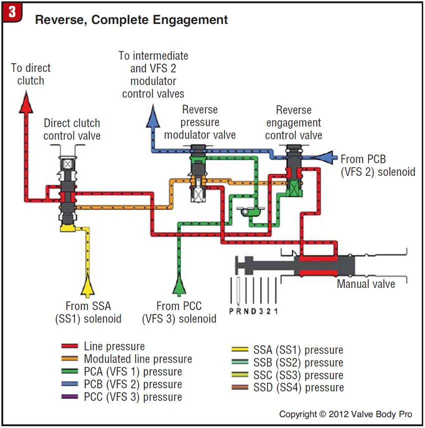
PCC pressure (green) is also directed to the bottom of the reverse-engagement control valve (Figure 3). As the PCC amperage is lowered by the PCM, PCC pressure increases. As PCC pressure increases it overcomes PCB pressure (blue) at the top of the reverse-engagement control valve, moving it up and opening the passage for main line pressure to enter the direct-clutch drum. This is the inertia phase of the direct-clutch engagement. The complete engagement takes about two seconds.
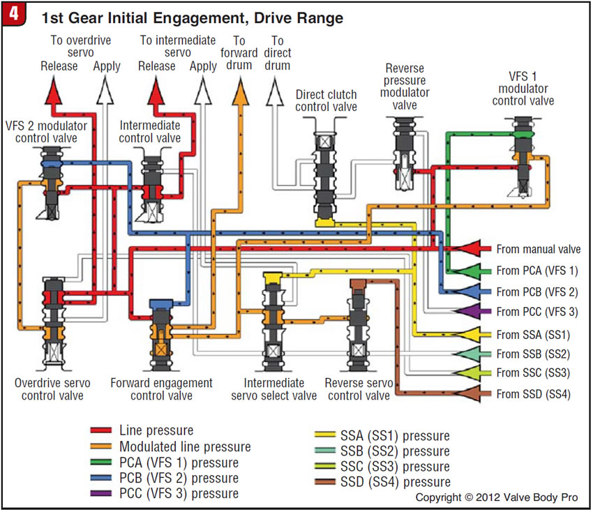
Now let’s look at the forward engagement (Figure 4). When Drive is selected, the transmission range sensor sends a signal to the PCM that Drive was selected. The PCM modulates variable-force solenoid 2 (PCB) with about 0.5 amp, which produces VFS 2 pressure (blue). This pressure acts on top of the forward-engagement control valve, which prevents main line pressure from the manual valve from entering the forward-clutch drum. The PCM starts to lower the amperage of the PCA solenoid, which starts to increase VFS 1 pressure (orange) at the VFS 1 modulation valve. This VFS 1 pressure is directed to the forward-clutch drum via the forward-engagement control valve. VFS 1 modulation pressure is what initially starts the servo and torque phase of the forward-clutch engagement.
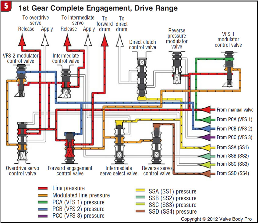
As VFS 1 modulated pressure (orange) is entering the forward-clutch drum (Figure 5), it is also acting on the bottom of the forward-engagement control valve. As the amperage to the PCA solenoid is lowered, VFS 1 modulated pressure increases. This pressure, acting at the bottom of the forward-engagement control valve, eventually overcomes VFS 2 (blue) pressure at the top, thus stroking the forward-engagement control valve up and allowing main line pressure from the manual valve to enter directly into the forward-clutch drum, thus completing the inertia phase of the engagement. The complete engagement takes about two seconds.
We hope this information will help you better diagnose those common forward and reverse engagement problems so prevalent on this unit and answer the question someone asked me not so long ago: How can a bad transmission range sensor keep this transmission from engaging forward or reverse?
Jesse Zacarias is the owner of Elec-Tran Diagnostics (www.electrandiagnostics.com) in Gilroy, Calif.