R&R Tech
- Subject: Malfunction in shift indicator, hard shifts
- Unit: 4L30-E
- Vehicle Application: 1998 Honda Passport
- Essential Reading: Diagnostician, R & R
- Author: Randy Peterson, Certified Transmission
What started out as a fairly simple fix turned into a “Nightmare on Oak Street”!
The vehicle involved was a 1998 Honda Passport 4WD with a 3.2-liter V-6 and 4L30-E transmission. The shift indicator in the cluster was not functioning properly, and the transmission was shifting hard. The indicator showed P in Park and 1 in D3, D2 and D1, and it didn’t light up any other time. This seemed to be pretty straightforward, since the mode switch (range sensor) has a high failure rate.
We bought and installed a new mode switch, and we still had the same problem. Well, I was wrong – not the mode switch. Now it was time to start the real work.
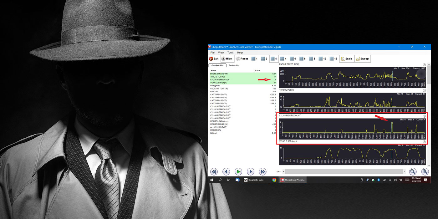
On this particular vehicle there was no data stream on our trusty scan tool, so pinpoint testing was the next step in the process.
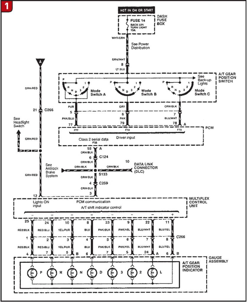
I printed the wire diagrams and familiarized myself with the locations and connectors. The system is a little more complex than some. The mode switch sends information to the PCM and to the alarm and relay control unit (ARCU), aka multiplex control unit. The PCM uses the information to regulate transmission operation, and the ARCU sends the information to the instrument-panel cluster.
First things first, though. I cleaned the science experiment on the battery terminals, then moved on to checking the powers and grounds. How many times have I skipped these steps only to get bitten by it later?
The PCM is below the center of the dash under the console. The ARCU is above the right kick panel (it was definitely hidden). I gained access to both modules. Not only do you need power to the mode switch, but also there needs to be power to the ARCU. Next, it’s time to break out the DVOM. The backup lamps and turn signals worked, which meant the fuse was good. I checked for B+ at the mode switch. There was B+ to the mode switch, B+ and ignition B+ to the ARCU. I checked the grounds from the PCM and the ARCU to the battery; grounds were good.

With the powers and grounds testing good, I needed to confirm whether I was getting signals from the mode switch to the PCM and ARCU. The mode switch has four internal switches. Power comes into the switch on pin 8, and as the lever is moved it directs power through the internal switches.
- Pin 8 (light blue): B+ from the backup/turn-signal fuse
- Pin 2 (white): effective in P, N, 3, L
- Pin 5 (purple): effective in P, R, 3, 2
- Pin 6 (gray): effective in R, N, D, 3
- Pin 7 (orange/black): effective in D, 3, 2, L
Pin 8 (light-blue wire) was B+ from the 15-amp backup/turn-signal fuse. When testing each pin, you should see continuity in its respective ranges. I also tested the voltage from the mode switch at the PCM and ARCU with them disconnected. Pins 5, 7 and 2 tested OK. Pin 6 tested open in all ranges. Bingo – found the problem! The new mode switch must be defective.
I bought a new mode switch and installed it. The indicator was functioning correctly now and the shifts were good. We always perform a final road test before the vehicle is delivered to the owner. For the first seven miles all was well; then, as I turned down the home stretch, the indicator went blank and the transmission wouldn’t shift. What happened? Everything was working so well.
I limped it back to the shop. Running the lever through the ranges, I had the same problem as before. What did I miss? I ran through the test again and found an open on pin 6. What’s going on?
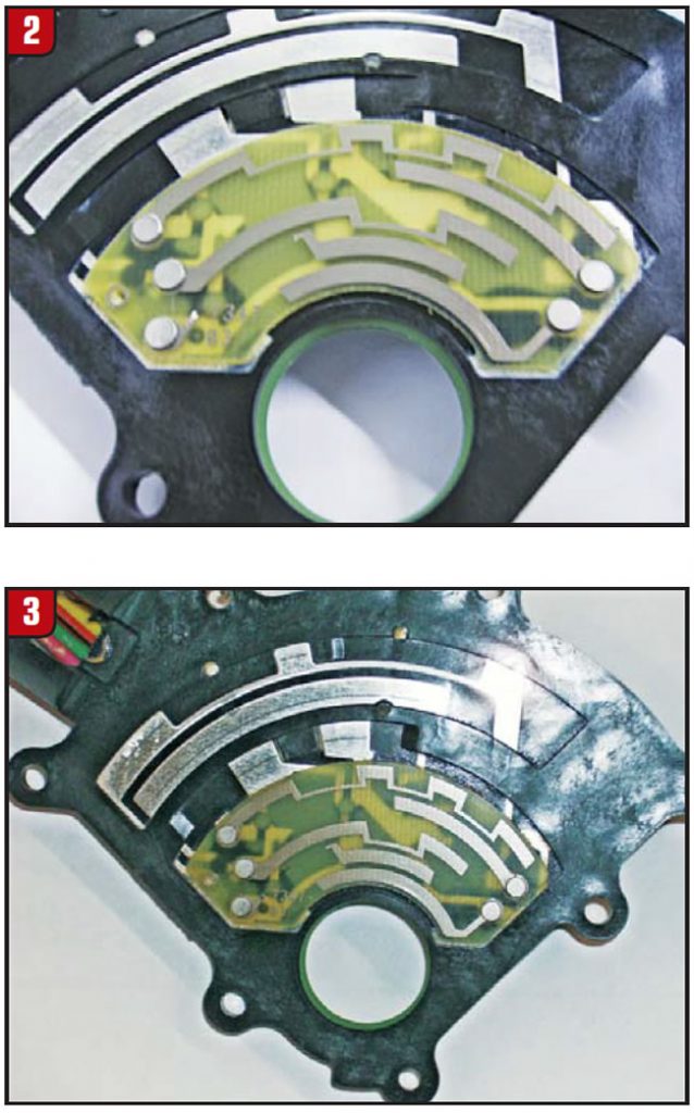
I took the mode switch apart and there it was – a piece of the thin metal used on the circuit board to make the slide connection was missing. The only thing I could think of was that there must be too many amps on that circuit.
I took the mode switch off and took it apart. There was a piece of the printed circuit missing. It was acting as a fuse. When the circuit was overloaded, the solder strip would fail with less than the 15 amps for which the fuse is rated. With the circuit going through the PCM and ACRU with B+, it’s probably a good thing the mode switch failed.
I used a fused jumper (5-amp fuse) with an ammeter inline to test the load on pins 5, 6 and 7. Pins 5 and 7 had 0.012-amp draw, but pin 6 blew my 5-amp inline fuse. I disconnected the ARCU, put in another fuse and blew the fuse again. I disconnected the PCM, and it blew that fuse. I knew I had a short to ground somewhere.
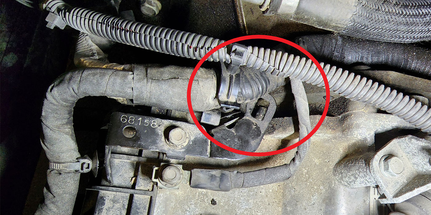
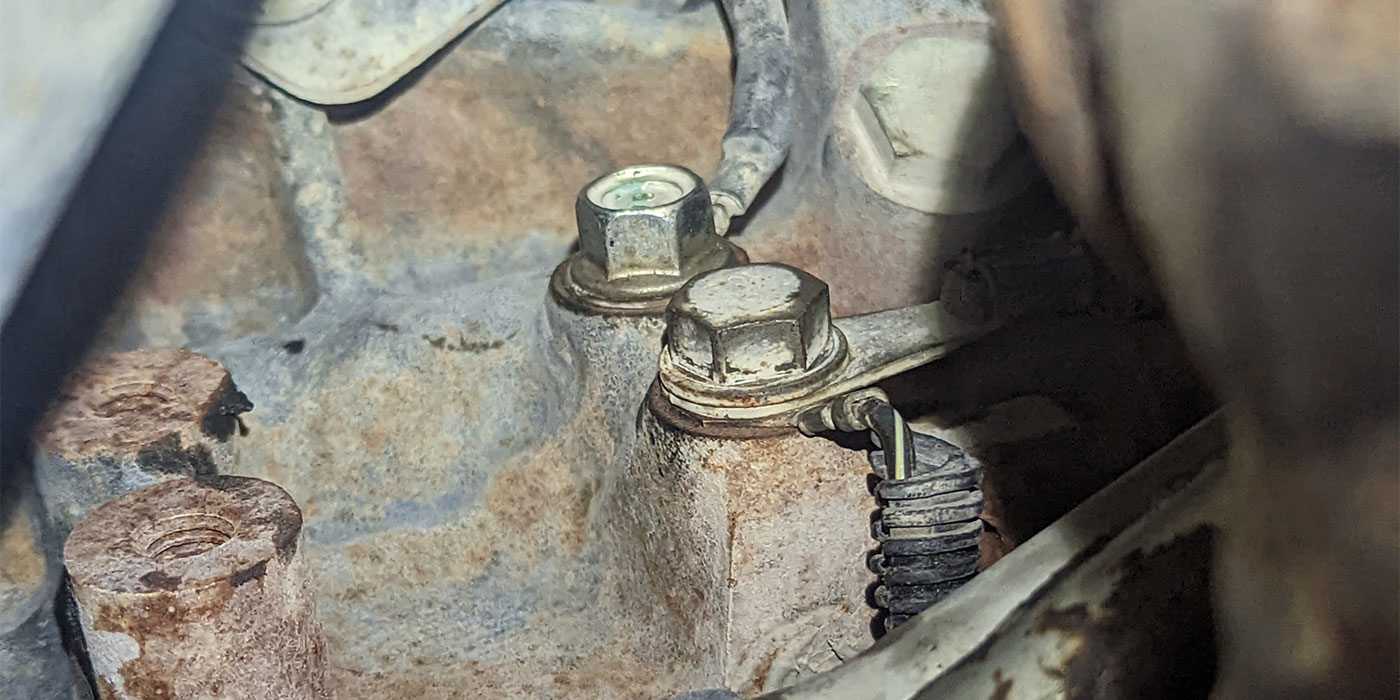
I started at the mode switch. The wire harness passes by the lower-left side of the bellhousing with a shield to protect the harness. I removed the shield, and there it was: a shiny piece of copper staring at me. The shield had rubbed through the conduit, tape and, finally, the insulation, causing the short. I repaired the wire, taped the harness and installed a new piece of conduit. At the same time I bent the shield so there were no sharp edges to wear through again. I retested the circuit and put on a new mode switch, and this time it passed the 20-mile final road test.
Apparently, moving the harness around during the previous mode-switch replacement must have been enough to move the bare wire away from the shield for a time. Then, after the vehicle was driven, the vibrations moved it back to its original resting place and shorted to ground.
In actuality, it was the mode switch that failed initially, but I made an assumption that a part had failed without determining why it failed. Like most of us, I put a part on and when that didn’t work I then did the diagnosis. Diagnosis should be the first step, not the second or last thing we think to do.
The good doctor says, “A good cure begins with a good diagnosis.” This beats what the bad doctor says: “The operation was successful, but the patient died.”