It’s a tale as old as time. A vehicle comes in and, despite having been recently repaired by another shop, the vehicle owner’s concern is still present. In the case of this story, the vehicle came from a local shop we work closely with. The truck in question is a 66,000-mile 2006 Chevrolet Silverado 2500 HD with the 6.6L engine and the LCT1000 transmission. The concern from our partner shop is that when cold, the truck won’t shift past first gear, and when warmed up it shifts normally.
Luckily, they provided a copy of the repair order. It showed that they had replaced both pressure control solenoids and listed some trouble codes including P0711 (transmission fluid temperature sensor performance), P0776 (pressure control solenoid 2 – stuck off), and P2723 (pressure control solenoid 1 – stuck off).
Armed with that information, I began with an under-hood inspection of the vehicle as well as a fluid level and condition check. Next, I plugged in the scan tool to perform my own code scan to see if anything had been overlooked. I found trouble codes in multiple modules. In the TCM I found P0776 and P0731 (incorrect first gear ratio), but in the BCM, TCCM and DDM I found U1024 (lost communication with transmission control system) stored.
From there I printed out freeze frame data and software calibration numbers, to see if they were up to date and to gather as much information as possible. On the road test I experienced a few things that I didn’t expect. Within only two blocks of the shop I experienced hard shifting, the shift indicator disappeared, the CEL came on, and the truck went into limp mode with codes P0711 and P0776 stored in the TCM and U1024 in other modules.
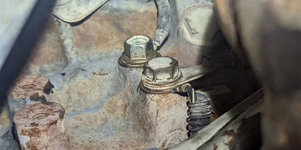
Upon returning to the shop, I performed the under-vehicle inspection, which included checking the transmission case connector for fluid intrusion as well as a visual inspection of TCM grounds G102 and G103 on the passenger side of the engine. (See Figure 1, above).
They both looked good, but I still disassembled and cleaned the mating surfaces and eyelets. The transmission cooler lines were leaking on the truck, but fluid was full and red. Since the initial inspection proved inconclusive, it was time to recommend and authorize additional time for further testing and research. The customer agreed to that and left the vehicle with us.
I started by looking over the recorded data from the original road test and making sure my TCM calibrations were up to date. Surprisingly, I had no fluctuation in transmission fluid temperature that would indicate a reason why P0711 would set. From there I double-checked code definitions. Most of the codes (other than P0711 and U1024) indicated a possible internal transmission failure. What really stood out to me were the setting conditions for P0776 and P2723: the TCM detected an incorrect on-coming ratio.
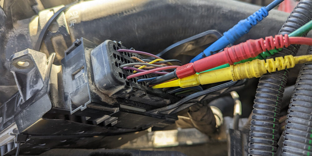
Next, I went for low-hanging fruit: I performed a battery and charging test to rule out any ripple that could cause an issue with the speed sensor inputs. The vehicle passed that test. I felt that it was time to get out the scope and take a deeper dive into what information was coming in/out of the TCM, so I back probed the TCM power, ground and temperature sensor voltage wires. (See Figure 2).
The truck continued to malfunction, set communication and pressure control solenoid codes, and go into limp mode even though there was no loss of TCM power or ground. I did not have any voltage fluctuations or codes reset for transmission temperature (P0711). Next, I moved my probes to verify the commands for the pressure control solenoids. Everything seemed to be in order.
At this point I was certain that we needed a replacement TCM to correct these issues. But before making that decision, I wanted something a little more conclusive. I began digging through ATRA bulletins, TSB articles and any other resource I had at my disposal.
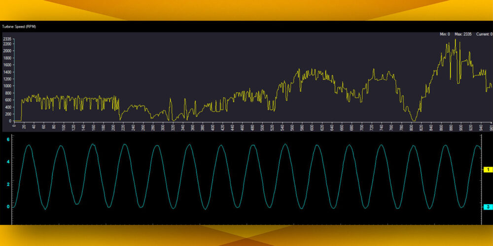
I kept thinking about the setting conditions defined as “TCM detected an incorrect on-coming ratio.” Another road test was in order so I could pay closer attention to the turbine, input and output speed sensors this time. That is when I saw something odd.
It appeared that the turbine speed was choppy. I saved a movie of the turbine speed signal and moved my scope probe to turbine speed signal. When I back probed the circuit, the signal was a smooth sine wave. (See Figure 3).
With all the issues this vehicle was exhibiting, I had a strong feeling that the TCM was our culprit from the beginning. However, just throwing more parts at the truck was not going to make me feel like I had done my due diligence. With information that was a little more concrete I was ready to make my recommendation for a new TCM, but there was only one problem: a new module was not available for purchase. Our service manager reached out to a couple of used part suppliers we work with and still could not find even a used module nearby.
A few weeks went by, and a call came in to say that a used module had been sourced. The customer brought the truck back in and I installed and reprogrammed the replacement controller. Everything worked great on the final road test. The turbine speed signal PID was now smooth, and the transmission shifted perfectly again.
We corrected the leaking transmission cooler lines, and all was well for the vehicle owner. (See Figure 4).
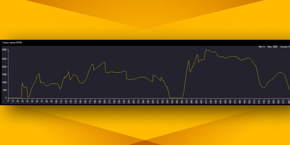
Recommending a replacement module always leaves me a little uneasy, especially when the only information you can prove is input and output conditions are correct for the vehicle. Seeing the turbine signal PID as bad as it was, as well as the scope pattern without any drop-outs, made me feel a lot more confident about being able to take care of the customer correctly the first time.
Read more stories in our R&R Tech series here.
Sean Mahoney has been a part of the Certified Transmission team for more than 10 years. He is ASE-Certified and enjoys the challenges that come with diagnosing a vehicle. He currently works at Certified’s Overland Park, Kansas location as a technical adviser.