TASC Force Tips
- Author: Ed Lee, Deltrans
The axis or centerline of an engine is the imaginary line around which the rotating mass revolves. The torque converter also has a centerline. Torque-converter rebuilders will tell you how important it is to maintain this centerline and to keep all surfaces perpendicular to this line. Transmissions also have a centerline. Most technicians learn early on the importance of good bushings and good bushing surfaces. Good bushings and their mating surfaces help to maintain a proper centerline to prevent seal and sealing-ring leaks.
Unfortunately, the art of keeping the engine, torque converter and transmission on the same centerline seems to have been lost sometime in the mid-1950s. Until that time, shop manuals of most automobile manufacturers included the proper procedure for checking and adjusting the centerline. For some unknown reason, this information ceased to be included, and the technology was seemingly lost over the years. Having a proper centerline was important then and is just as important today.
Most automobile manufacturers agree that the centerline of the transmission must be within 0.005 inch of the centerline of the engine. Any remanufactured engine should have the centerline checked. This is especially important if the engine was line-bored. Any vehicle that has experienced repeated flywheel cracking and/or flywheel breakage most likely will not be on a proper centerline. Some starter-related failures and noises also could be related to centerline problems. The most-common centerline-related problems that transmission technicians have to face probably will be leaks and/or pump noises.
To check your centerline, you will need a dial indicator and some type of bellhousing with a machined surface to read against. General Motors’ vehicles are the easiest to check, because standard-shift bellhousings are easy to obtain. The stick-shift bellhousings have a machined surface that centers the front-bearing retainer of the standard-shift transmission in the bellhousing.
On small-block V-8 Fords, the C-4 bellhousing that bolts to the pump works very well. On large-block Fords, the large-block FMX bellhousing works equally well. On the 2.8-, 2.9- and 4.0-liter Ford V-6 engines, the C-4 bellhousing that fits 1974-78 V-6 Mustangs is a lifesaver.
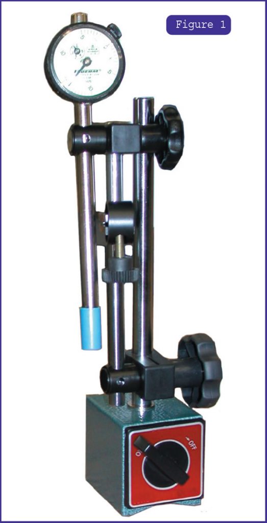
If you have a magnetic base for your dial indicator, simply place the magnetic base on the flywheel and rest the indicator pointer on the inner machined surface of the bellhousing (see Figure 1). Adjust the dial to zero, and then rotate the crankshaft, by hand, one complete revolution. If the centerline is correct, the needle will not go above 0.010 inch. One-half of the reading on the dial is how far the centerline is off. Remember that up to 0.005 inch is satisfactory for most manufacturers.
If you do not have a magnetic base, you will have to fabricate something to hold the dial indicator in the proper position. At least two manufacturers are making offset dowel pins. Moroso Performance Products of Guilford, CT, is one, and Lakewood Industries of Cleveland is another. Pins with offsets of 0.007 inch, 0.014 inch and 0.021 inch are available. You can buy these from most good performance and speed shops.
Adjusting the offset dowel pins is not an easy task. Here are some hints to make the job easier.
Place the dowel pins in the block with the slots out. Now put the bellhousing onto the block, and install the bolts above and below the dowel pins on each side. Zero the indicator and rotate the crankshaft one revolution. The dial most likely will travel above and below the zero mark. Rotate the crankshaft until the needle has traveled to the point farthest below zero. Reset the gauge to zero. Now turn the crankshaft until the gauge reaches its highest reading, and stop. Loosen all four bellhousing attaching bolts just enough to turn the dowel pins. Start with the dowel pin closest to the gauge plunger, and turn it so that the gauge needle moves toward zero. You will want the needle to move one-fourth of the travel back to zero. For example, if your total travel is 0.020 inch, rotate the dowel pin until the needle travels 0.005 inch toward zero.
Now adjust the opposite dowel pin an additional one-fourth of the travel, or 0.005 inch. Reset your gauge to zero and rotate the crankshaft one revolution. You should be closer to your centerline each time you repeat this procedure. It usually takes about three attempts. When your centerline is correct, mark the dowel pins at the 12 o’clock position before you remove the bellhousing. This will allow you to reposition them correctly if they come loose when the bell housing is removed.
The owner of one large East Coast transmission shop said the centerline-related problems cost his shop about $60,000 a year. His centerline problems are not unique. We hope this information will help solve some of your related problems.

The TASC Force (Technical Automotive Specialties Committee) is a group of recognized industry technical specialists, transmission rebuilders and Sonnax Industries Inc. technicians.


