
Shift Pointers
- Author: Pete Luban, ATSG Technical Supervisor
Once upon a time in a transmission shop, transmissions were built and installed and the vehicles road tested and delivered – life was good.
Notice that the preceding paragraph starts with “once upon a time,” which is how a fairy tale begins. The transmission business is very different today, and technicians find themselves having to deal with a number of vehicle operating systems that they once thought would never concern them. In other words, today’s transmission technicians are rapidly becoming electrical and drivability technicians, because these “other” systems (that is one of the choices on your scan-tool menu) directly affect how a transmission performs. This is one of those stories.
Since the inception of OBD-II, Ford vehicles with EEC-V computer control systems have used the mass-air-flow (MAF) sensor as a primary input for fuel-system control. This engine-load device is responsible for long-term fuel trim and for injector pulse rate.
You might be thinking at this point, “So what does this mean to me? I don’t work on fuel systems.” Don’t be so quick to say “not me.”
When a MAF sensor malfunctions, it can do so in a very subtle way. It can create an erratic or incorrect signal on initial take-off, which can cause an elongated shift. It can deliver an incorrect signal at higher engine speed, which can create shudder that could be mistaken for torque-converter-clutch (TCC) problems. It can cause coast-downshift clunks, especially as the vehicle is coming to a stop. It can even cause a slide-bump shift. It is a major input for electronic pressure control that will result in elevated line pressure.
So, do you still not work on fuel-control systems?
From the symptoms that I’ve mentioned, it is easy to see how you could waste a lot of time on diagnosis of problems that appear to be caused by the valve body, solenoids, accumulator, or a clutch or band.
The standing joke in our industry used to be, “If you have a problem with a Ford, change the MLPS; it fixes everything.” From the hotline calls we are receiving here at ATSG, I think we are going to have to change that to, “Change the MAF sensor; it fixes everything.”
There is a fairly simple test that you can perform to determine whether the MAF sensor is the culprit causing some of these symptoms: Unplug it! The PCM now will use the throttle-position sensor (TPS) as a backup input, and the powertrain control module (PCM) now will calculate engine load using the TPS signal.
You can see this in action by watching the scan-tool parameter for the MAF sensor with the sensor disconnected; you will still have a MAF signal. This is the calculated signal the PCM is creating by using the TPS signal as a backup.
The actual number of bad MAF sensors is small. The major problem is contamination of the sensor. We are fixing more shift-related complaints on Ford vehicles simply by cleaning the MAF sensor.
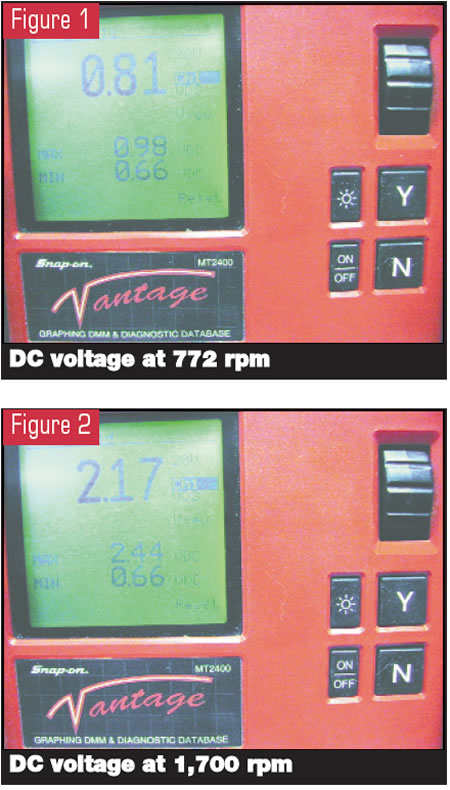
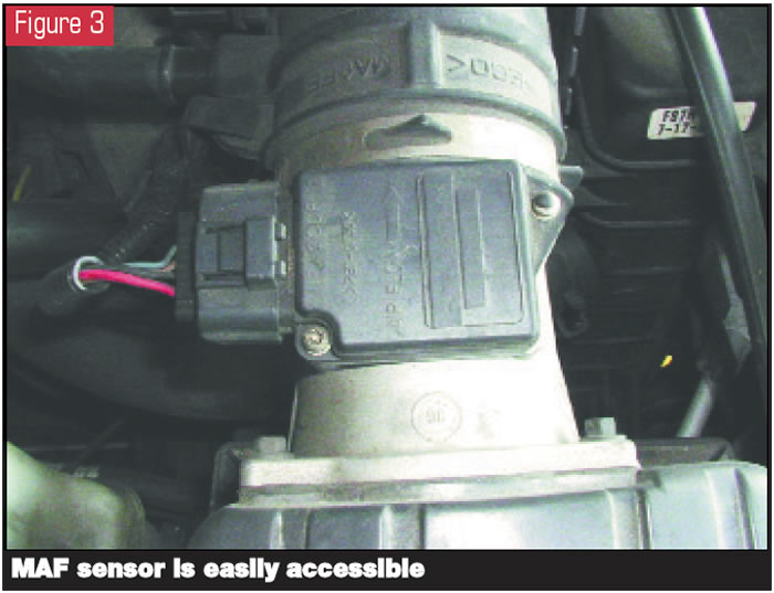
Ford MAF sensors use what is referred to as the “hot-wire” system. A wire stretched across the sensor’s flow tube is heated to 3,920° F (2,000° C). The amount of electrical power required to keep this wire at 3,920° is translated into a DC-voltage signal return that rises proportionately with engine speed (see Figures 1 and 2, which show voltage readings at 772 rpm and 1,700 rpm, respectively) and is sent to the PCM. That’s why the signal is corrupted when the air-delivery duct from the air filter is torn. This allows cooler air into the MAF sensor, significantly cooling the hot wire.
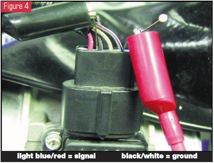
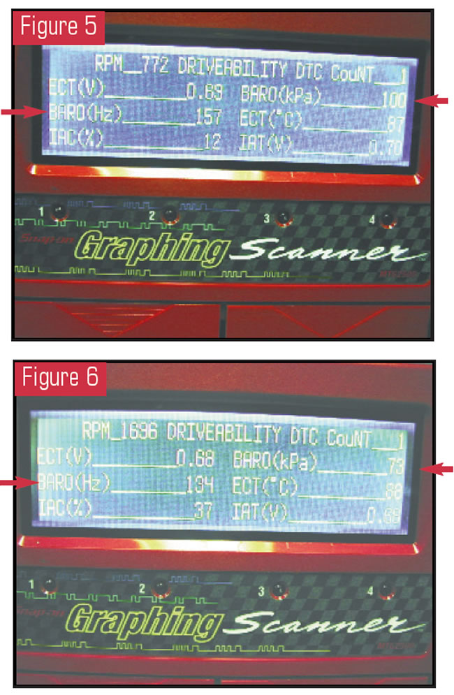
You can easily check the MAF voltage signal at the sensor, as it usually is out in the open (see Figure 3). Place your meter leads on the signal wire (light blue/red) and the sensor’s ground circuit (black/white) at the sensor, which is easy to get to (see Figure 4).
An incorrect voltage signal may not be obvious, since it may be difficult to actually see when the signal becomes corrupted. Use your multimeter’s MIN/MAX feature as an aid.
Another way to check the signal is use the PCM’s method of looking at this sensor, which is viewed on the scan tool as “BARO.”
Before checking the BARO parameters, take the vehicle for a road test and open the throttle to wide open three or four times so that the PCM can update the BARO values, especially if the vehicle went from one altitude to another.
There are two parameters for the BARO: Hertz and kPa. Figure 5 shows these parameters with engine speed at 772 rpm, and Figure 6 shows the display at 1,700 rpm. You can use the movie or snapshot feature of your scan tool to get more of a real-time value. The vehicle really doesn’t have a baro sensor; these are calculated processed parameters that allow you to see what the PCM sees.
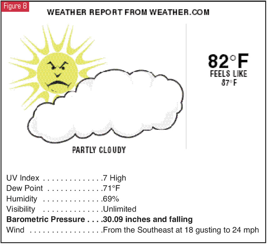
You can use the chart in Figure 7 to check your scan-tool display against the correct values. The values in the chart are based on barometric pressure. So does this mean you need to have a barometer? No, not really. Figure 8 is a typical weather report for my local area that I get by connecting to the Internet and going to the Web site www.weather.com.
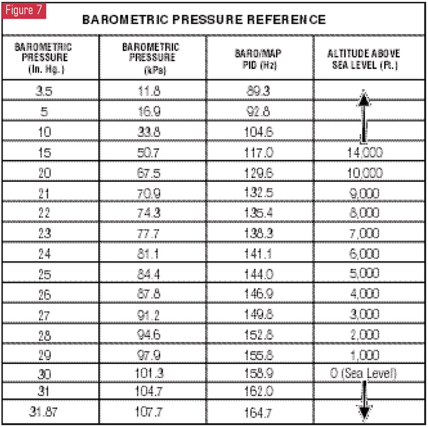
Notice on the scan-tool display in Figure 5 that the kPa display is at 100. The chart in Figure 7 shows that 100 kPa equates to sea level, which is about right for south Florida, and a hertz reading of 158.9. The scan-tool display in Figure 5 shows 157 Hz – close enough.
The chart indicates that my baro reading at these values should be about 30 inches. The weather report in Figure 8 indicates 30.09 inches – close enough. As you can see, this is fairly accurate.
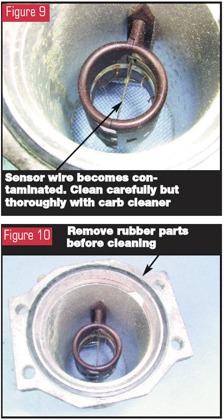
Now let’s talk about cleaning the MAF sensor. It is extremely important to clean the wire in the sensor’s flow tube (see Figure 9). This wire must be cleaned thoroughly. Actual contact with the wire for purposes of cleaning is not recommended, because it can be damaged easily. The best way I have found to do this is by spraying carburetor cleaner on the wire until it is spotless. The better you clean it, the better it will work.
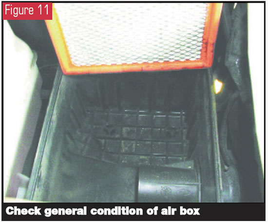
Be sure to remove any rubber parts, such as the mounting O-ring (see Figure 10). Carb cleaner really screws up rubber.
One final point: Make certain you check the air-filter housing (see Figure 11). It might be loaded with leaves, twigs or perhaps even a furry woodland creature. Worst of all, it could have oil in it from the PCV system that would quickly contaminate the MAF sensor you just finished cleaning. Also, do the customer a favor and change the air filter if necessary.
You will be amazed at how many of your shift-related complaints will disappear when you perform this simple service, not to mention adding to your profits.


