Torque Converter Tech Tips
- Author: Ed Lee
In a torque converter, clutch-release clearance (CRC) is the distance that the torque-converter-clutch (TCC) piston travels from the release to the apply position. This distance is also the amount of free play that is available to the clutch or clutches when the TCC piston is in the release position.
In a transmission, the rules that govern the setting of the CRC are very straightforward. Giving a clutch pack 0.008 to 0.009 inch of clearance for each friction usually will yield good results, although there are a few exceptions. The 4L30-E overdrive clutch – along with a few others – uses a little extra clearance as part of its accumulation action. But in the long run, you’d be fairly safe using the rule of 0.008 to 0.009 inch per friction across the board.
In a torque converter, the rules are quite different. Many additional factors beside interference clearance come into play. The in-and-out flow of some converters is affected by CRC and must be considered. TCC apply feel is a factor on some converters. On others, the CRC is restricted because of the amount of available travel (captive clutch) or by a secondary obligation (retaining the springs on an A500 or A518). In units like the 722.6 and RE5R05A, there is an actual clutch pack in the converter, similar to those found in a transmission.
If you exclude the captive-clutch and clutch-pack-style converters, CRC falls into one of two configurations:
- Converters with turbine hubs that do not come into contact with the cover.
- Converters with turbine hubs that do rest against the cover.
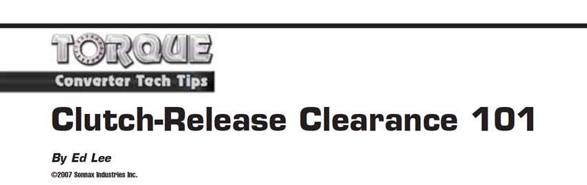
On converters where the turbine hub does not come into contact with the cover, the converter endplay is the CRC. On this type of torque converter, you can check the endplay/CRC with some tools that are already on the market (see figures 1a and 1b).
With one tool, the converter is inverted in a fixture and the tapered mandrel of the tool pushes the turbine up, and a dial indicator measures the travel when the tool is released. On the other tool, a shaft expands, locking it into the turbine-hub splines, and the up-and-down movement of the shaft is read on the dial indicator.
Checking factory converters with good friction material and minimal wear to thrust surfaces will give you a good idea of the CRC that the OE manufacturer built into the converter. On this type of converter you can see the volume of transmission lube oil (cooler flow) decrease if the clearance is too tight. For that reason, release clearance/endplay is seldom less than 0.030-0.035 inch. Clearances of 0.045 to 0.055 inch are commonly found on this type of converter.
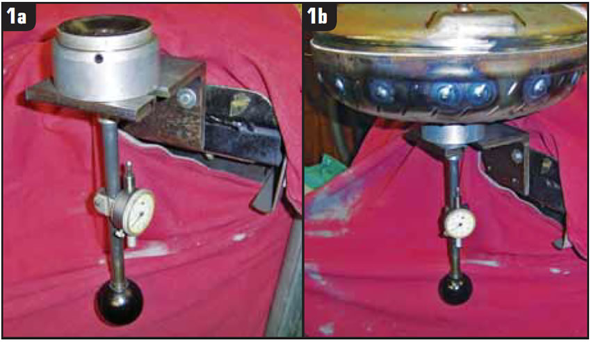
On the converters with turbine hubs that contact the cover, the CRC is calculated in a different manner. Measure the distance from the clutch-release stop on the piston to the cover when the piston is in the apply position, and subtract that figure from the distance from the cover to the clutch-release stop on the turbine hub (see figures 2 and 3).
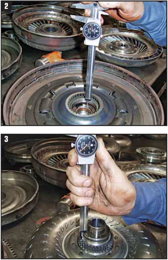
On a single-clutch application, when a single-sided friction material is bonded to the cover or piston, the piston is the only part placed against the cover. Keep in mind that this may include more than just the piston in a multi-clutch configuration.
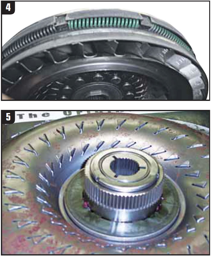
On most import converters with this type of setup, the CRC will range from 0.030 to 0.035 inch. For domestic units, there are as many converters that break this rule as those that follow it. The Chrysler rear-wheel-drive converters – A500 and A518, for example – rely on the turbine to keep the damper springs in the TCC piston (see Figure 4). For this reason the clearance is only 0.025-0.035 inch. The Chrysler 618 converter has captive damper springs, but it also uses the closer clearance of 0.025-0.035 inch.
The GM 298mm converter falls into this category even though the conical washer separates the turbine hub and cover, but unlike the Chrysler converters the GM 298mm converter needs more clearance, not less. The normal hydraulic forces in this converter are trying to push the piston toward the cover, so the piston will release only to a position that will allow a full flow of release oil to pass in front of the piston. Too much release clearance should not be a problem with this converter, and most are in the range of 0.060-0.070 inch.
It is extremely important that you understand how the OEMs built the converter. Do not be fooled by the bearing on the front of the turbine hub of the 4R100 converter (see Figure 5), or the witness marks on the turbine hub of the CD4E or similar import converters. Measure your clearance, and if you have positive clearance between the cover and the turbine hub, you must build the converter as if they do not touch. The witness marks are the result of the turbine hub touching the cover because of piston deflection.
Most CRC issues can be monitored with a flow-measuring device, such as the Sonnax Sonnaflow®. If the CRC is too close, you will see low flow when the TCC piston is in the release position. If the CRC is too loose, you will see a large dip/loss in flow as the available line pressure or converter feed oil (transmission-dependent) is filling the area and pushing the TCC piston to the apply position. Transmission technicians have been dealing with clearance issues in the 604 and 606 transmissions in the form of CVI (clutch volume index) values for years. These same CVI values are also the basis for the adaptive learn systems that are on many vehicles today.

Ed Lee is a Sonnax Technical Specialist who writes on issues of interest to torque-converter rebuilders. Sonnax supports the Torque Converter Rebuilders Association. Learn more about the group at www.tcraonline.com. ©2008 Sonnax Industries Inc.


